In this series of tutorials, we will see how to drive a multitude of relays with a NodeMCU32S microcontroller and 74HC595 shift registers. We will then see how to address each relay individually. Finally, we will create a web interface to control each relay via the internet. This project is a good basis to develop a home automation system for your home.
This tutorial can be applied to any microcontroller. You will need to be careful to modify the connection diagram and code to suit your use.
Material
- NodeMCU 32S
- Breadboard
- Jumper cable
- 8 relay module
- Shift register 74hc595
Principle
To control the 8 relay module, 8 digital outputs of the microcontroller must be reserved. In order to save the number of inputs/outputs of the microcontroller, different integrated circuits can be used. In particular, the shift register. The shift register 74HC595 has 8 programmable outputs, which can be set to 0 or 5V and only requires 3 digital inputs. This solution is therefore ideal to allow us to control the relays and keep the microcontroller outputs for other functions.
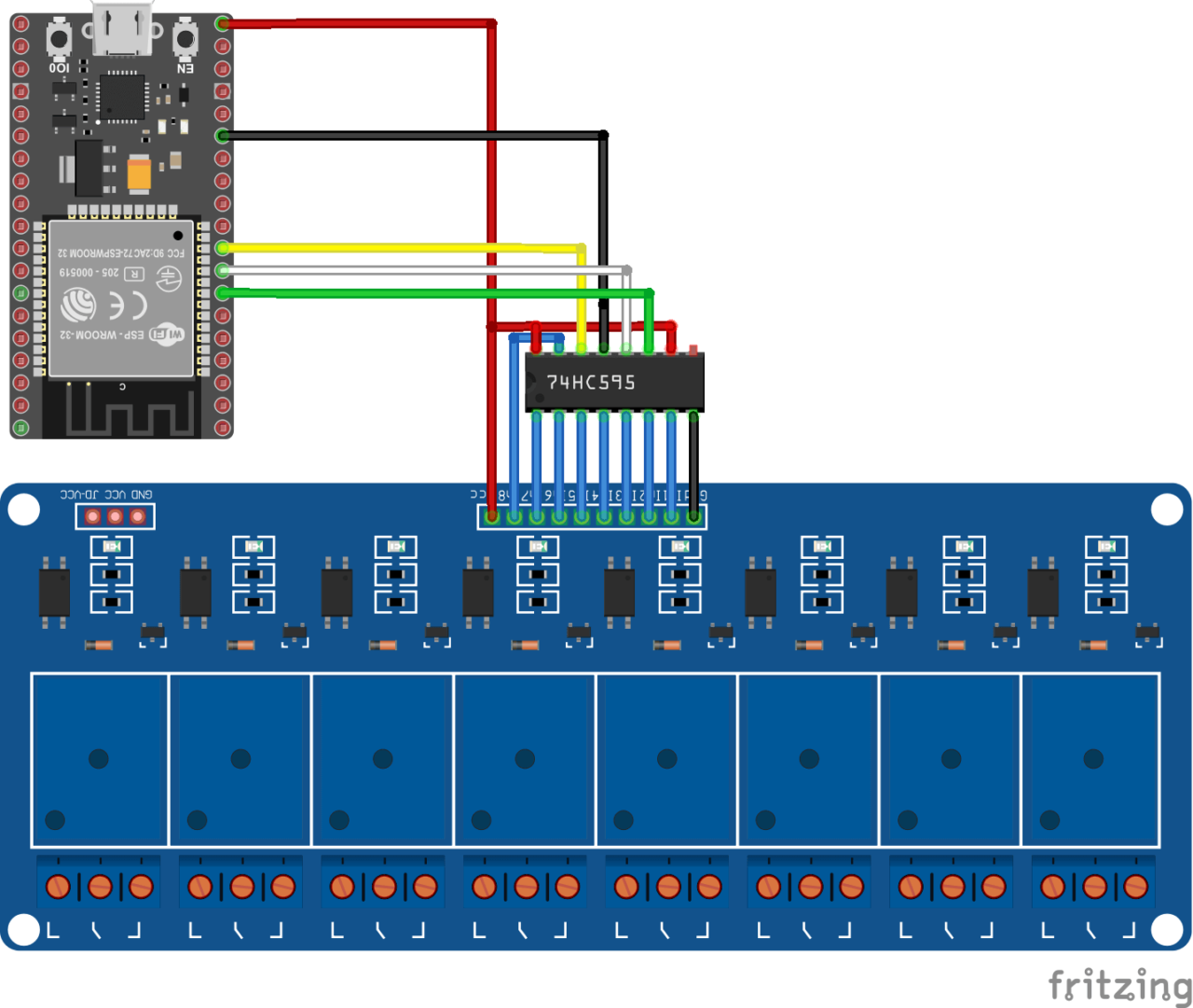
Schematic
To control the shift register, the NodeMCU is connected as follows:
- GND integrated circuit ground
- Vcc power supply pin. Usually connected to 5V
- SH_CP or RCLK connected to pin 33
- ST_CP or SRCLK connected to pin 32
- DS or SER connected to pin 25
The outputs of the integrated circuit 74HC595 (Q0-Q7) are directly connected to the inputs of the 8 relay module. In this tutorial we do not use the Enable (OE) and Reset (MR) pins.
- OE Output enable, activates LOW. Pin connected to GND to activate the outputs.
- MR Master reset, active LOW. Reset pin. Connected to 5V
Attention: The outputs of a microcontroller are current limited. To drive so many relays, it is strongly recommended to use an external voltage source.

Code
In the following code, we will first define the basic functions to manage the shift register. Then we will operate the relays one by one using a for loop.
//Constants
#define number_of_74hc595s 1
#define numOfRegisterPins number_of_74hc595s * 8
#define SER_Pin 25
#define RCLK_Pin 33
#define SRCLK_Pin 32
//Variables
boolean registers [numOfRegisterPins];
void setup(){
//Init Serial USB
Serial.begin(115200);
Serial.println(F("Initialize System"));
//Init register
pinMode(SER_Pin, OUTPUT);
pinMode(RCLK_Pin, OUTPUT);
pinMode(SRCLK_Pin, OUTPUT);
clearRegisters();
writeRegisters();
delay(500);
}
void loop(){
writeGrpRelay();
}
void clearRegisters(){/* function clearRegisters */
//// Clear registers variables
for(int i = numOfRegisterPins-1; i >= 0; i--){
registers[i] = HIGH;//LOW;
}}
void writeRegisters(){/* function writeRegisters */
//// Write register after being set
digitalWrite(RCLK_Pin, LOW);
for(int i = numOfRegisterPins-1; i >= 0; i--){
digitalWrite(SRCLK_Pin, LOW); int val = registers[i];
digitalWrite(SER_Pin, val);
digitalWrite(SRCLK_Pin, HIGH);
}
digitalWrite(RCLK_Pin, HIGH);
}
void setRegisterPin(int index,int value){/* function setRegisterPin */
////Set register variable to HIGH or LOW
registers[index] = value;
}
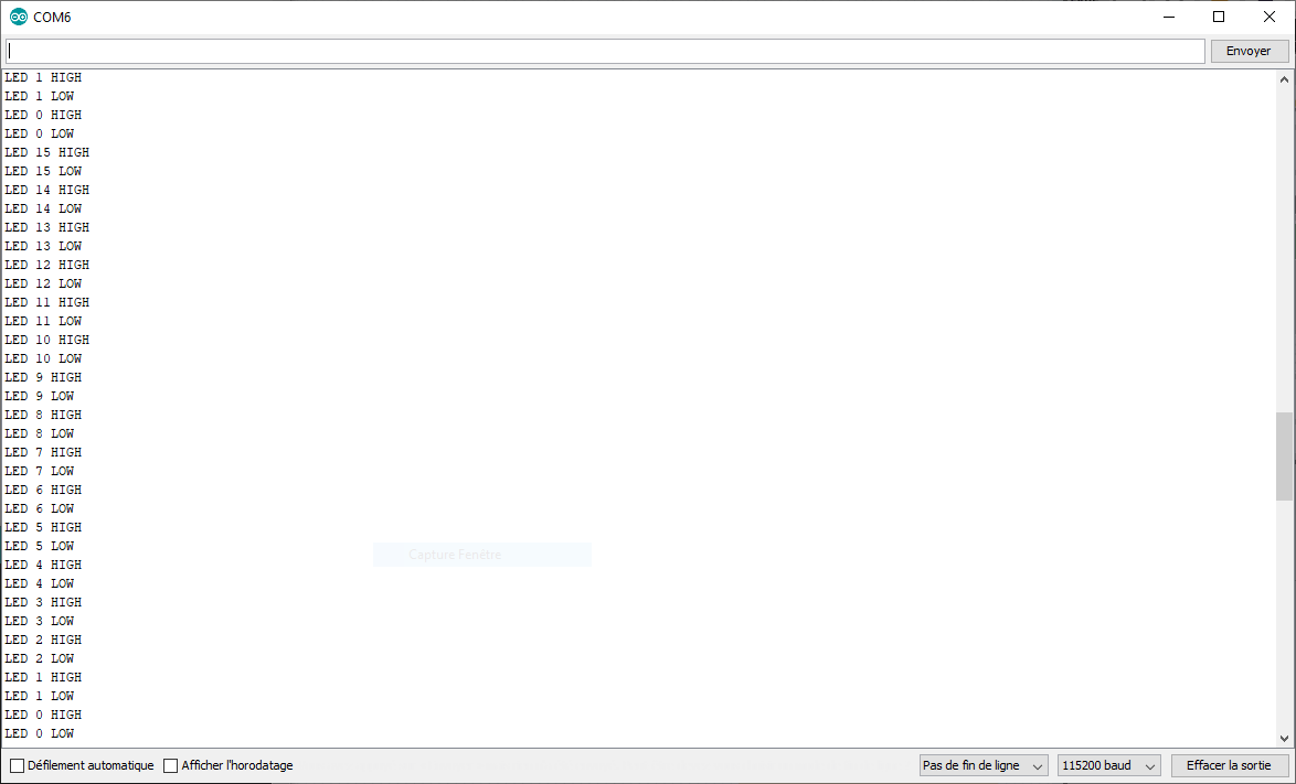
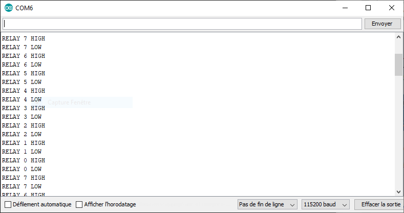
void writeGrpRelay(){/* function writeGrpRelay */
for(int i = numOfRegisterPins-1; i >= 0; i--){
Serial.print(F("Relay "));Serial.print(i);Serial.println(F(" HIGH"));
setRegisterPin(i, LOW);
writeRegisters();
delay(200);
Serial.print(F("Relay "));Serial.print(i);Serial.println(F(" LOW"));
setRegisterPin(i, HIGH);
writeRegisters();
delay(500);
}
}
Results
Once the components have been correctly connected and the code loaded into the microcontroller, the relays should activate one after the other.

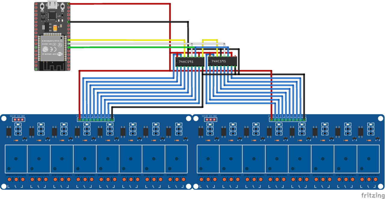
Bonus: Control 16 relays with two shift registers.
Schematic

Code
The beauty of this code is that to make it work with a second shift register you only need to change the parameter:
#define number_of_74hc595s 2
Results