
The RGB LED provides a wide range of colors. It is composed of three mini LEDs, red, green and blue (hence their name RGB); close enough for their lights to mix. Therefore, it is piloted in the same way as three independent LEDs.
For instance, it can be used to create a light ambiance at home or to give some information to the user regarding the status of a system (Green – all is good, Blue – processing, Red – there is an error).
Equipment
- Arduino x1
- M/M wires x3
- Prototyping board x1
- Resistor 220 Ohm x1
- RGB LED x1
RGB LED diagram
The color control pins (R, G, B) are connected to PWM outputs of the Arduino board.If you use other outputs than the PWMs outputs (the digital outputs), the transient colors will not appear and the LED will jump from one color to another.
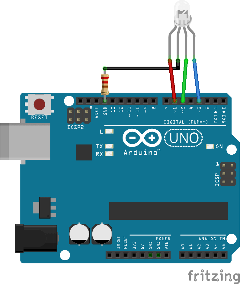

Generally, the values of current supported by the LEDs are not available. Do not forget to put a resistor between the cathode and the ground of the Arduino to protect the LED and the Arduino output.
Management code for an RGB LED
In this example, we move from one color to another gradually. For this, we vary the values R, G, B which we send to the corresponding pins.
In this case, it is more practical and readable to use a function that assigns the PWM value to the correct output for each color. To do so we create the function lightRGB that takes 3 integers as inputs, which are the pwm command, and write this value to the RGB pins.
void lightRGB(int r, int g, int b){
  analogWrite(RED, r);
  analogWrite(GREEN, g);
  analogWrite(BLUE, b);
}
Once the function created, it can be used in the main code (in loop function) and control three outputs with one line of code. Here is the complete code.
// Pins
#define BLUE 3
#define GREEN 5
#define RED 6

#define delayTime 10 // fading time

int MAX_LUM = 255;
int redVal,greenVal,blueVal;

void setup()
{
  pinMode(RED, OUTPUT);
  pinMode(GREEN, OUTPUT);
  pinMode(BLUE, OUTPUT);
  digitalWrite(RED, HIGH);
  digitalWrite(GREEN, LOW);
  digitalWrite(BLUE, LOW);
}

void loop()
{
  redVal = MAX_LUM; // choose a Val between 1 and 255 to change the color.
  greenVal = 0;
  blueVal = 0;

  for(int i = 0; i < MAX_LUM; i += 1) // fades out red bring green full when i=255
  {
    redVal -= 1;
    greenVal += 1;
    lightRGB(redVal, greenVal, blueVal);
    delay(delayTime);
  }

  redVal = 0;
  greenVal = MAX_LUM;
  blueVal = 0;

  for(int i = 0; i < MAX_LUM; i += 1) // fades out green bring blue full when i=255
  {
    greenVal -= 1;
    blueVal += 1;
    lightRGB(redVal, greenVal, blueVal);
    delay(delayTime);
  }

  redVal = 0;
  greenVal = 0;
  blueVal = MAX_LUM;

  for(int i = 0; i < MAX_LUM; i += 1) // fades out blue bring red full when i=255
  {
    // The following code has been rearranged to match the other two similar sections
    blueVal -= 1;
    redVal += 1;
    lightRGB(redVal, greenVal, blueVal);
    delay(delayTime);
  }
}

void lightRGB(int r, int g, int b){
  analogWrite(RED, r);
  analogWrite(GREEN, g);
  analogWrite(BLUE, b);
}
Controlling a RGB LED seems trivial but it’s a great exercise when beginning to play with Arduino. One RGB might be of little use to create light effects. In this case you may have to use adressable LED strips.
Application
- Change the color of the LED according to the room temperature
- Create a lamp that changes color controlled by IR remote
Source
Find other examples and tutorials in our Automatic code generator
Code Architect