

In some projects it may be interesting to establish a serial communication between Raspberry Pi and Arduino. This makes it possible to couple the computing power and wireless interfaces of the Raspberry Pi with the inputs/outputs and the Arduino collection of modules. The first example that comes to mind is the use of this system for home automation in which the Raspberry Pi will host the control interface and intelligence and the Arduino will act as a programmable automaton acting on the components at the end of the chain (light, radiator, fan, sensors, etc.).
We will see in this tutorial how to set up a serial communication between Raspberry Pi and Arduino via the USB port. In this article we use the Arduino UNO card but it can be adapted to other types of cards with a serial connection (Nano, Mega, Feather, EPS32, ESP8266, etc.).
Prerequisite: Serial communication with Arduino,Remote access to Raspberry Pi with VNC
Hardware
- Computer
- Arduino UNO
- Raspberry Pi 3B+
- USB A Male / USB B Male
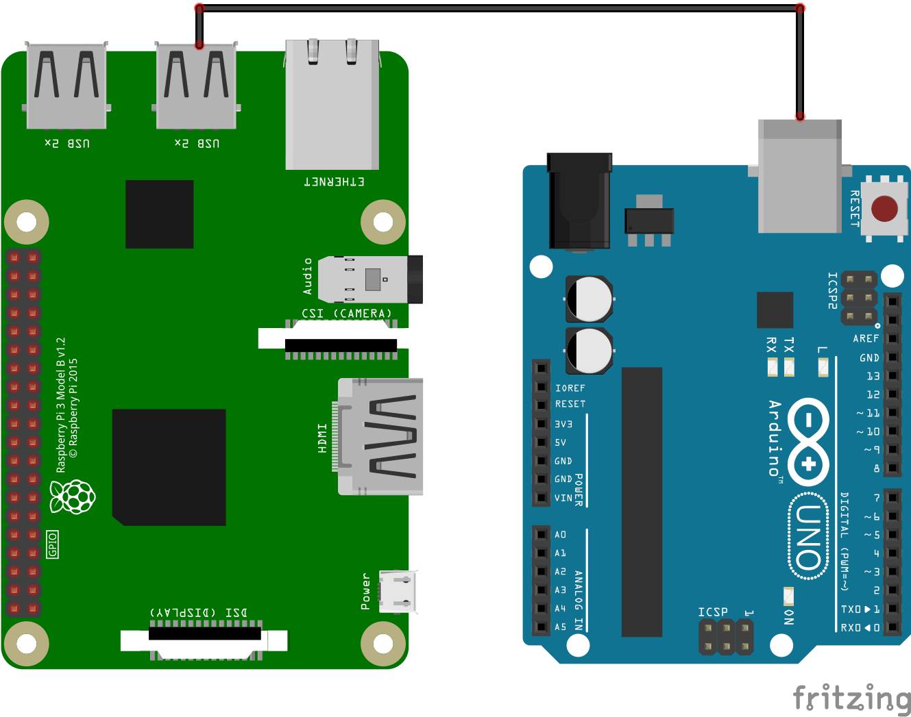
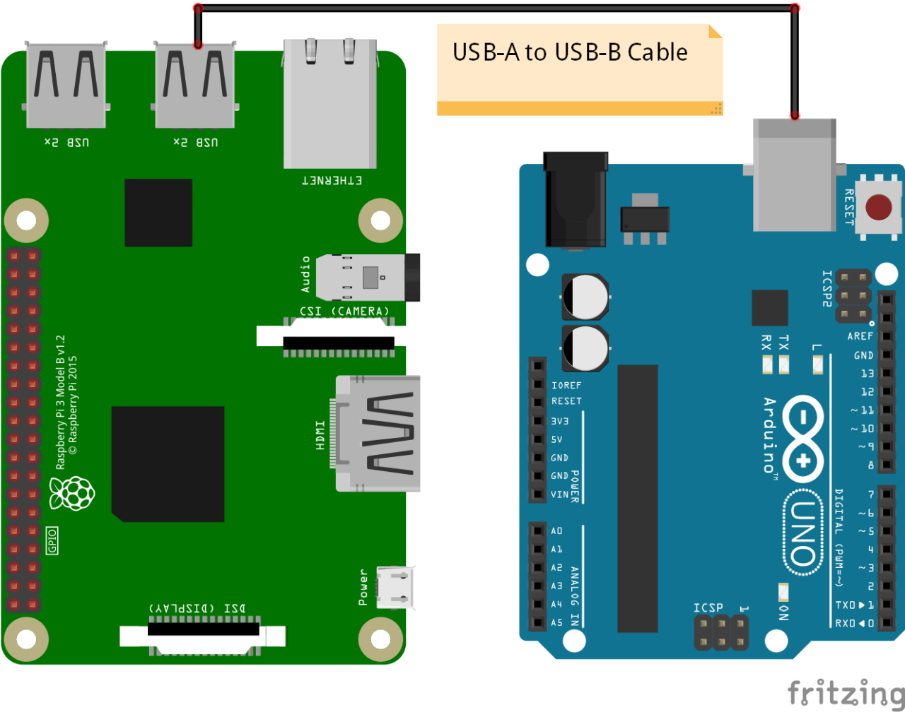
Wiring diagram
To establish serial communication between Raspberry Pi and Arduino, simply connect them with a suitable USB cable. In our case, we use a Raspberry Pi 3B+ and an Arduino UNO. So we need a USBA Male to USB B Male cable.

It is also possible to create serial communication by using the Rx/Tx pins of both components. In this tutorial we will focus on the USB connection.
- Tx GPIO14(RPI) <-> Rx 0(Arduino)
- Rx GPIO15(RPI) <-> Tx 1(Arduino)
- GND (RPI) <-> GND(Arduino)
Raspberry Pi configuration
We remind you that in order to be able to use your Raspberry Pi without screen or keyboard, the VNC remote connection must be configured.
To use the serial interface of the Raspberry Pi, it must be enabled in the configuration menu. To do this, enter the following command in a terminal:
sudo raspi-configIn the menu, select “5 – Interfacing Options” then “P6 Serial” and validate.
Once the connection has been made, you can check the devices connected to the serial port by typing the command in the terminal:
lsusbThe Raspberry Pi returns the list of devices connected to the USB ports.
pi@raspberrypi:~ $ lsusb
Bus 001 Device 002: ID 2341:0043 Arduino SA Uno R3 (CDC ACM)
Bus 001 Device 001: ID 1d6b:0002 Linux Foundation 2.0 root hub
To find the name of the port to which the Arduino is connected, we use the command:
dmesg | grep "tty"This command returns the system messages related to the serial ports. You had to find the name of the port in the last messages. In our case the port name is ttyACM0.
pi@raspberrypi:~ $ dmesg | grep "tty"
[    0.000000] Kernel command line: coherent_pool=1M 8250.nr_uarts=1 bcm2708_fb.fbwidth=1824 bcm2708_fb.fbheight=984 bcm2708_fb.fbswap=1 smsc95xx.macaddr=B8:27:EB:23:CF:07 vc_mem.mem_base=0x1ec00000 vc_mem.mem_size=0x20000000  console=ttyS0,115200 console=tty1 root=/dev/mmcblk0p7 rootfstype=ext4 elevator=deadline fsck.repair=yes rootwait quiet splash plymouth.ignore-serial-consoles
[    0.000636] console [tty1] enabled
[    0.951553] 20201000.serial: ttyAMA0 at MMIO 0x20201000 (irq = 81, base_baud = 0) is a PL011 rev2
[    0.954393] console [ttyS0] disabled
[    0.954466] 20215040.serial: ttyS0 at MMIO 0x0 (irq = 53, base_baud = 31250000) is a 16550
[    0.954570] console [ttyS0] enabled
[    5.378641] systemd[1]: Created slice system-serial\x2dgetty.slice.
[ 1455.402071] cdc_acm 1-1:1.0: ttyACM0: USB ACM device
[ 1581.980257] cdc_acm 1-1:1.0: ttyACM0: USB ACM device
Installation of the Arduino IDE on Raspberry Pi
To install the Arduino IDE on Raspberry Pi, it is best to go through the terminal. Simply enter the following lines of code:
mkdir ~/Applications
cd ~/Applications
wget https://downloads.arduino.cc/arduino-1.8.9-linuxarm.tar.xz
tar xvJf arduino-1.8.9-linuxarm.tar.xz
cd arduino-1.8.9/
 ./install.sh
rm ../arduino-1.8.9-linuxarm.tar.xz
This will then allow you to program the Arduino directly from the Raspberry Pi.
Code
Code Arduino
The library used for serial communication on the Arduino side is the same as for communicating with the serial monitor, the Serial.h library that we know well. Make sure that the communication speed is the same for both devices (baudrate=9600) otherwise the communication will not work.
String nom = "Arduino";
String msg;

void setup() {
  Serial.begin(9600);
}

void loop() {
  readSerialPort();

  if (msg != "") {
    sendData();
  }
  delay(500);
}

void readSerialPort() {
  msg = "";
  if (Serial.available()) {
    delay(10);
    while (Serial.available() > 0) {
      msg += (char)Serial.read();
    }
    Serial.flush();
  }
}

void sendData() {
  //write data
  Serial.print(nom);
  Serial.print(" received : ");
  Serial.print(msg);
}
Code Python
In this tutorial we will use the Python language on the Raspberry Pi side. The library used to manage the serial communication is the serial library.
#!/usr/bin/env python
# -*- coding: utf-8 -*-
# lsusb to check device name
#dmesg | grep "tty" to find port name

import serial,time


if __name__ == '__main__':

	print('Running. Press CTRL-C to exit.')
	with serial.Serial("/dev/ttyACM0", 9600, timeout=1) as arduino:
		time.sleep(0.1) #wait for serial to open
		if arduino.isOpen():
			print("{} connected!".format(arduino.port))
			try:
				while True:
					cmd=input("Enter command : ")
					arduino.write(cmd.encode())
					#time.sleep(0.1) #wait for arduino to answer
					while arduino.inWaiting()==0: pass
					if  arduino.inWaiting()>0:
						answer=arduino.readline()
						print(answer)
						arduino.flushInput() #remove data after reading
			except KeyboardInterrupt:
				print("KeyboardInterrupt has been caught.")
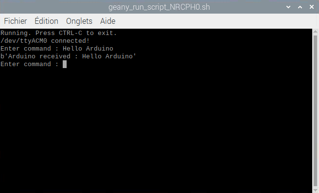
Result
The Raspberry Pi sends the order “Hello Arduino” to the Arduino, and the Arduino replies with its name and the order received.

Practical example
Once communication is established between Raspberry Pi and Arduino, the interesting thing is to control the Arduino’s I/O and retrieve the sensor values. In this example, we will define different commands:
- one to retrieve sensor values
- one for switching the LED on and off on pin 13
Code Arduino
The Arduino returns data when it receives the “data” command and switches the LED connected to pin 13 on and off according to the “led0” and “led1” commands.
const int ledPin=13;
String nom = "Arduino";
String msg;

void setup() {
  Serial.begin(9600);
  pinMode(ledPin,OUTPUT);
}

void loop() {
  readSerialPort();

  if (msg == "data") {
    sendData();
  }else if(msg=="led0"){
    digitalWrite(ledPin,LOW);
    Serial.println(" Arduino set led to LOW");
  }else if(msg=="led1"){
    digitalWrite(ledPin,HIGH);
    Serial.println(" Arduino set led to HIGH");
  }
  delay(500);
}

void readSerialPort() {
  msg = "";
  if (Serial.available()) {
    delay(10);
    while (Serial.available() > 0) {
      msg += (char)Serial.read();
    }
    Serial.flush();
  }
}

void sendData() {
  //write data ledState x sensor1 x sensor2
  Serial.print(digitalRead(ledPin));
  Serial.print("x");
  Serial.print(analogRead(A0));
  Serial.print("x");
  Serial.print(analogRead(A1));
}
Code Python
#!/usr/bin/env python
# -*- coding: utf-8 -*-
# lsusb to check device name
#dmesg | grep "tty" to find port name

import serial,time


if __name__ == '__main__':
	print('Running. Press CTRL-C to exit.')
	with serial.Serial("/dev/ttyACM0", 9600, timeout=1) as arduino:
		time.sleep(0.1) #wait for serial to open
		if arduino.isOpen():
			print("{} connected!".format(arduino.port))
			try:
				while True:
					cmd=input("Enter command (data,led0 or led1): ")
					arduino.write(cmd.encode())
					#time.sleep(0.1) #wait for arduino to answer

					while arduino.inWaiting()==0: pass
					if  arduino.inWaiting()>0:
						answer=str(arduino.readline())
						print("---> {}".format(answer))
						if cmd=="data":
							dataList=answer.split("x")
							print("led state : {}".format(dataList[0]))
							print("Analog input A0 : {}".format(dataList[1]))
							print("Analog input A1: {}".format(dataList[2]))

							arduino.flushInput() #remove data after reading

			except KeyboardInterrupt:
				print("KeyboardInterrupt has been caught.")
Once the two codes have been uploaded and launched, it can be seen that when the “data” command is entered into the terminal, Arduino returns many bytes containing the sensor values. It is possible to separate this response into a list using the split() function and the “x” character and, in this way, recover the sensor values and the status of the led. With this code we can control the status of the LED on pin 13.

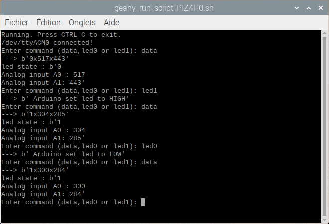
By modifying this code, you will be able to control and observe any entry/exit of the Arduino on the Raspberry Pi.
Application
- Create a graphical user interface (GUI) under Raspberry Pi to drive an Arduino and retrieve sensor values
Sources
Find other examples and tutorials in our Automatic code generator
Code Architect