

The PCA9685 module is a 16-channel controller that can control 16 PWM outputs via I2C communication. It allows, among other things, to free inputs and outputs of your microcontroller and to drive up to 16 LEDs or servomotors (or any other module taking a PWM signal as input) using two pins (SCL and SDA) while keeping the pins of your microcontroller for other modules such as sensors.
Prerequisite: Driving a servomotor with Arduino

Hardware
- Computer
- ArduinoUNO
- USB A Male to B Male cable
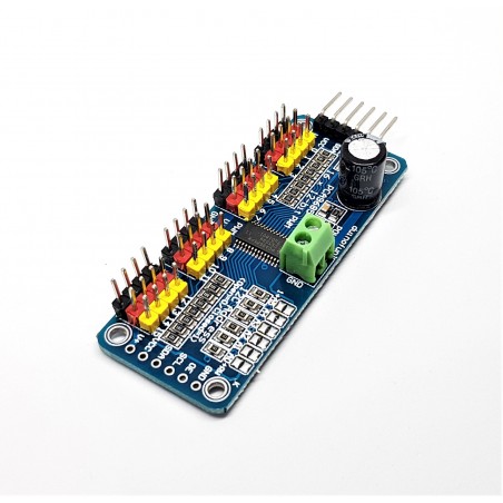
- PCA9685Module
Principle of operation
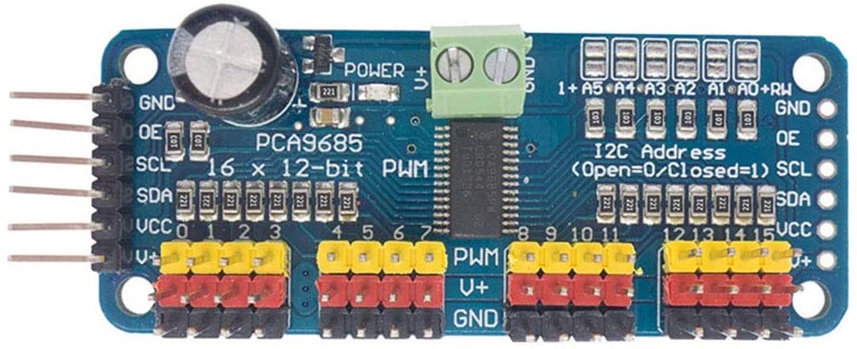
The module is based on the PCA9685 controller, which allows PWM outputs to be controlled using I2C communication and an integrated clock. This module has 6 bridges to select the board address and to place on the same bus up to 62 controllers for a total of 992 actuators (available addresses 0x40 to 0x7F).
It can drive PWM outputs with adjustable frequency and 12-bit resolution. The module is compatible with 5V and 3.3V microcontrollers.

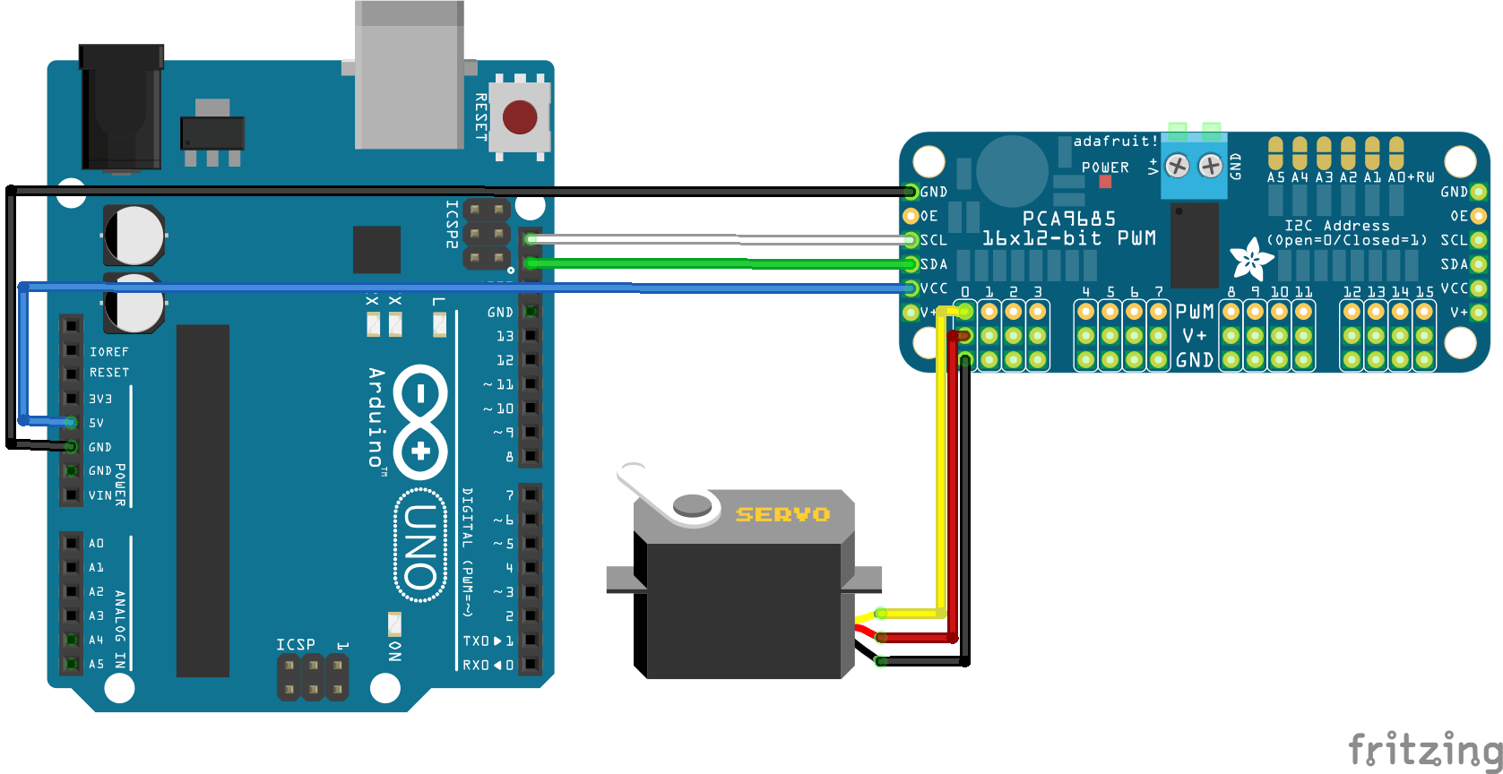
Diagram
The module is equipped with an I2C bus and a power input. The I2C bus is connected as follows:
- Pin A5 or SCL to the SCL pin of the module
- Pin A4 or SDA to the SDA pin of the module
- Pin 5V to the Vcc pin of the module
- Pin GND to the GND pin of the module In this tutorial we use the Arduino UNO board but it can be adapted to other microcontrollers. To do so, just adapt the I2C pins available on the microcontroller in question and possibly the code.
Code
To use the PCA9685 module, we use the library Adafruit_PWMServoDriver.h. PWM widths are usually given in microseconds over a period of 20ms (50Hz) but these values can change from one actuator to another and between vendors. You will have to modify the values in the code to adapt them to your actuator.
In our case, we use the MG90S actuator whose ranges are 400-2400µs over 20ms.
To set the PWM command, the library provides two functions: setPWM() and writeMicroseconds(). The writeMicroseconds() function allows us to use the constructor values directly. For the setPWM function, we need to find the corresponding pulse width on 4096 (2^12, 12bits).
Example: The frequency is 50Hz so a period of 20ms or 20000µs.
- pwmvalmin=400/20000×4096=81.92-> 90 rounding off with a safety margin
- pwmvalmax=2400/20000×4096=491.52 -> 480 rounding off with a safety margin
Which gives us the following equivalence:
- pca.writeMicroseconds(i,400) equals pca.setPwm(i,0,90)
- and pca.writeMicroseconds(i,2400) equals pca.setPwm(i,0,480)
It’s up to you to use the function that suits you best.
//Libraries
#include <Wire.h>//https://www.arduino.cc/en/reference/wire
#include <Adafruit_PWMServoDriver.h>//https://github.com/adafruit/Adafruit-PWM-Servo-Driver-Library

//Constants
#define nbPCAServo 16

//Parameters
int MIN_IMP [nbPCAServo] ={500, 500, 500, 500, 500, 500, 500, 500, 500, 500, 500, 500, 500, 500, 500, 500};
int MAX_IMP [nbPCAServo] ={2500, 2500, 2500, 2500, 2500, 2500, 2500, 2500, 2500, 2500, 2500, 2500, 2500, 2500, 2500, 2500};
int MIN_ANG [nbPCAServo] ={0, 0, 0, 0, 0, 0, 0, 0, 0, 0, 0, 0, 0, 0, 0, 0};
int MAX_ANG [nbPCAServo] ={180, 180, 180, 180, 180, 180, 180, 180, 180, 180, 180, 180, 180, 180, 180, 180};

//Objects
Adafruit_PWMServoDriver pca= Adafruit_PWMServoDriver(0x40);

void setup(){
//Init Serial USB
Serial.begin(9600);
Serial.println(F("Initialize System"));
pca.begin();
pca.setPWMFreq(60);  // Analog servos run at ~60 Hz updates
}

void loop(){
  pcaScenario();
}

void pcaScenario(){/* function pcaScenario */
////Scenario to test servomotors controlled by PCA9685 I2C Module
for (int i=0; i<nbPCAServo; i++) {
  Serial.print("Servo");
  Serial.println(i);
      //int middleVal=((MAX_IMP[i]+MIN_IMP[i])/2)/20000*4096; // conversion µs to pwmval
      //pca.setPWM(i,0,middleVal);
      for(int pos=(MAX_IMP[i]+MIN_IMP[i])/2;pos<MAX_IMP[i];pos+=10){
        pca.writeMicroseconds(i,pos);delay(10);
      }
      for(int pos=MAX_IMP[i];pos>MIN_IMP[i];pos-=10){
        pca.writeMicroseconds(i,pos);delay(10);
      }
      for(int pos=MIN_IMP[i];pos<(MAX_IMP[i]+MIN_IMP[i])/2;pos+=10){
        pca.writeMicroseconds(i,pos);delay(10);
      }
      pca.setPin(i,0,true); // deactivate pin i
    }
}

int jointToImp(double x,int i){/* function jointToImp */
////Convert joint angle into pwm command value

      int imp=(x - MIN_ANG[i]) * (MAX_IMP[i]-MIN_IMP[i]) / (MAX_ANG[i]-MIN_ANG[i]) + MIN_IMP[i];
      imp=max(imp,MIN_IMP[i]);
      imp=min(imp,MAX_IMP[i]);

 return imp;
}
Math behind jointToImp
The function joinToImp() does the same as the map() function in Arduino. It converts a value from a range to another following a linear equation.
imp=map(x,MIN_ANG,MAX_ANG,MIN_IMP,MAX_IMP);
We know that the relation between the angle and the impulsion width is linear, thus, we can describe this equation by
imp = a * x + b
The idea is to find the coefficients a and b. For this we need two equations. what we know is that :
- when x=MIN_ANG then y=MIN_IMP
- when x=MAX_ANG then y=MAX_IMP
Which leads to the following equations:
MIN_IMP = a * MIN_ANG + b
MAX_IMP = a * MAX_ANG + b
Working around those two equations, we can solve a and b in two steps:
- Substract equations
MAX_IMP - MIN_IMP = a * (MAX_ANG - MIN_ANG)
a = (MAX_IMP - MIN_IMP)/(MAX_ANG - MIN_ANG)
- Replace a in equation
MIN_IMP = (MAX_IMP - MIN_IMP)/(MAX_ANG - MIN_ANG) * MIN_ANG + b
b = MIN_IMP - (MAX_IMP - MIN_IMP)/(MAX_ANG - MIN_ANG) * MIN_ANG
We can then deduce the conversion equation
y = (MAX_IMP - MIN_IMP)/(MAX_ANG - MIN_ANG) * x + MIN_IMP - (MAX_IMP - MIN_IMP)/(MAX_ANG - MIN_ANG) * MIN_ANG
y = (x - MIN_ANG) * (MAX_IMP - MIN_IMP)/(MAX_ANG - MIN_ANG) + MIN_IMP
Applications
- Control the Quadrina6 robot
Sources
- http://adafruit.github.io/Adafruit-PWM-Servo-Driver-Library/html/class_adafruit___p_w_m_servo_driver.html#aa892432ed08e4b3892c8eb0478168dd8
- https://robojax.com/learn/arduino/robojax-PCA6985.pdf
- https://www.nxp.com/products/power-management/lighting-driver-and-controller-ics/ic-led-controllers/16-channel-12-bit-pwm-fm-plus-ic-bus-led-controller:PCA9685
- https://www.arduino.cc/en/reference/wire
- https://github.com/adafruit/Adafruit-PWM-Servo-Driver-Library
Find other examples and tutorials in our Automatic code generator
Code Architect