
Les microcontrôleur PIC sont des composants simples, économiques de taille et de performance variées, idéal pour des systèmes embarqués optimisés. Nous allons voir dans ce tutoriel comment les programmer avec la suite logiciel MPLAB.
Matériel
- Ordinateur
- PicKit4 ou 5
- PIC16F19156
- PIC breakout
- Module TTL-to-USB
Installation de la suite logiciel MPLAB X
Téléchargez et installez l’IPE et l’IDE MPLABX.
Installation d’un compilateur
Téléchargez et installez un compilateur adapté au microcontrôleur utilisé
| MPLAB XC Compilers | |
| XC8 | supports all 8-bit PIC and AVR (MCUs) |
| XC16 | supports all 16-bit PIC MCUs and dsPIC (DSCs) |
| XC32/32++ | supports all 32-bit PIC and SAM MCUs and MPUs |
Dans notre cas, nous utilisons un PIC16F (microcontrôleur 8 bit), nous installons donc le compilateur XC8.
N.B.: n’oubliez pas de l’ajoutez le chemin d’accès à vos variables d’environnement
Configurer un Projet
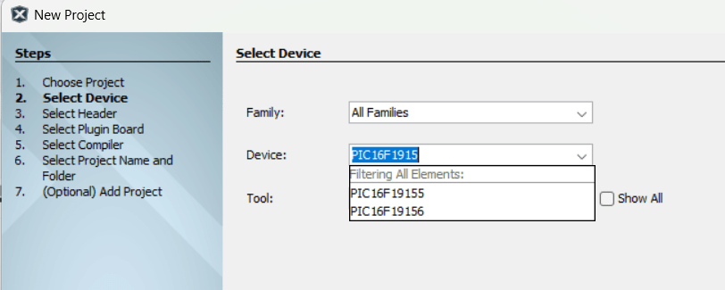
Dans le logiciel MPLAB, créez un nouveau porjet


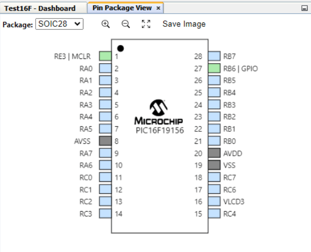
Sélectionnez ensuite l’appareil cible (ici: PIC16F19156)

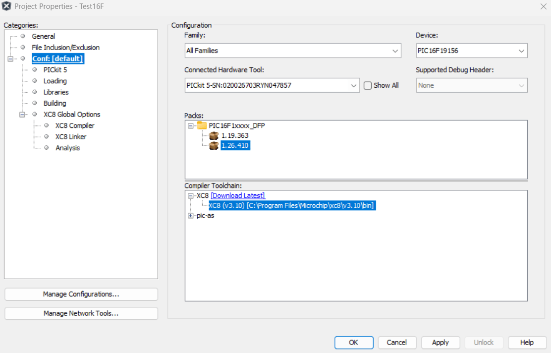
Vous pouvez ensuite choisir le compilateur (ici: xc8)


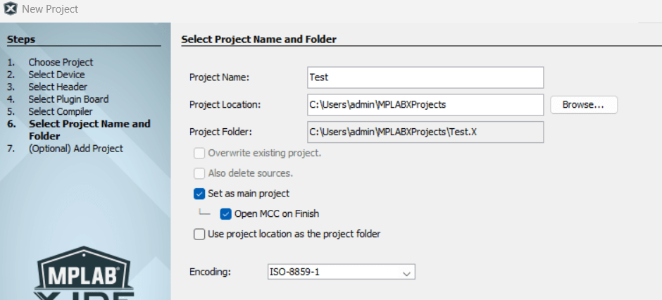
Enfin choisissez le nom du projet et l’emplacement de sauvegarde.

Lorsque vous configurez le projet, vous pouvez sélectionner un outil de compilation (PicKit ou simulator)

Se plonger dans les spécifications de l’appareil
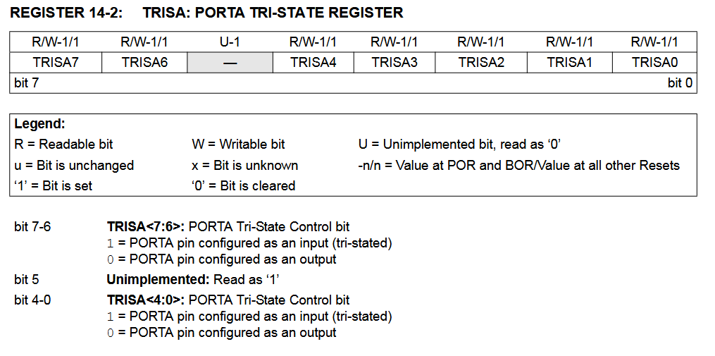
Pour pouvoir programmer un microcontrôleur avec du code embarqué, il est primordial de savoir se référer à la documentation technique afin de trouver et d’utiliser correctement les registres de configuration et de contrôle des différentes fonctions.
Ex: registre de configuration des broches du portA en entrée ou en sortie TRISA

Se familiariser avec la syntaxe du compilateur
Selon l’outil ou la version que vous utilisez, XC8 ou autre, la syntaxe et l’adressage des registres peut changer. Vous pouvez retrouver les définitions dans les fichiers entête à la racine de l’installation de MPLABX
C:\Program Files\Microchip\MPLABX\v6.25\packs\Microchip\PIC16F1xxxx_DFP\1.26.410\xc8\pic\include\proc\pic16f19156.h
Piloter une sortie numérique (LED)
/**
 * @file    main.c
 * @brief   Exemple LED sur PIC16F19156
 *          - LED1 (RB6) toggle toutes les 500 cycles
 *
 * @hardware:
 *          - PIC16F19156
 *          - LED1 : RC4 (pin 15)
 *
 */
#include <xc.h>
#include <stdint.h>
#include <stdio.h>
#include <string.h>

typedef uint8_t bool;
const bool true = 1;
const bool false = 0;

#define _XTAL_FREQ 4000000UL  // Oscillateur interne HFINTOSC = 4 MHz

// ==================== CONFIG BITS ====================
#pragma config WDTE = OFF        // IMPORTANT: if not reset
//#pragma config LVP = OFF        // IMPORTANT: Disable LVP for UART
//#pragma config WRTD = OFF  //EEPROM not write protected

// ==================== LED DEFINITIONS ====================
#define LED1   LATCbits.LATC4
#define LED1_TRIS   TRISCbits.TRISC4
#define LED1_ANSEL  ANSELCbits.ANSC4

/**
 * @brief Initialise LED1
 */
void led_init(void)
{
    // ---------------- LED1 setup ----------------
    LED1_ANSEL = 0;  // digital
    LED1_TRIS  = 0;  // sortie
    LED1       = 0;  // état initial

}

// ==================== MAIN ====================
void main(void)
{
    // ---------------- Initialisation -------------------
    led_init();

    // ---------------- Boucle principale ----------------
    uint16_t counter = 0;
    while(1)
    {
        if(counter % 500 == 0){
            LED1 ^= 1;  // toggle
        }
        counter++;
    }
}
Configurer un timer
/**
 * @file    main.c
 * @brief   Exemple Timer1 sur PIC16F19156
 *          - LED1 (RB6) toggle toutes les 100 ms via Timer1 interrupt
 *          - LED2 (RC3) et LED3 (RA1) toggle dans la boucle principale toutes les 1000 ms
 *
 * @hardware:
 *          - PIC16F19156
 *          - LED1 : RC4 (pin 15)
 *
 */

#include <xc.h>
#include <stdint.h>

#define _XTAL_FREQ 4000000UL  // Oscillateur interne HFINTOSC = 4 MHz

// ==================== LED DEFINITIONS ====================
// On définit directement LED1 comme LAT
#define LED1   LATCbits.LATC4
#define LED1_TRIS   TRISCbits.TRISC4
#define LED1_ANSEL  ANSELCbits.ANSC4

// ==================== TIMER1 VARIABLES ====================
uint8_t t1h_reload, t1l_reload;
char armed = 0;

/**
 * @brief Calcule le préchargement de Timer1 pour la période désirée (ms)
 * @param ms : période en millisecondes
 */
void Timer1_SetPeriod_ms(uint16_t ms)
{
    uint32_t ticks = (ms * 1000UL) / 8UL; // prescaler=8 ? tick=8us
    if (ticks >= 65536UL) ticks = 65535UL;

    uint32_t preload = 65536UL - ticks;
    t1h_reload = (uint8_t)(preload >> 8);
    t1l_reload = (uint8_t)(preload & 0xFF);
}

/**
 * @brief Initialise Timer1 et LED1
 */
void timer1_init(void)
{
    // ---------------- LED1 setup ----------------
    LED1_ANSEL = 0;  // digital
    LED1_TRIS  = 0;  // sortie
    LED1       = 0;  // état initial

    // ---------------- TIMER1 setup ----------------
    Timer1_SetPeriod_ms(600);  // 100 ms pour test

    // Source clock Timer1 = Fosc/4
    TMR1CLK = 0b0001;

    // Timer1 configuration : prescaler 1:8, sync internal, off
    T1CONbits.T1CKPS0 = 1;
    T1CONbits.T1CKPS1 = 1;  // prescaler 1:8
    T1CONbits.nSYNC   = 1;  // sync internal
    T1CONbits.TMR1ON  = 0;  // off while loading

    // Charger préchargement
    TMR1H = t1h_reload;
    TMR1L = t1l_reload;

    // Clear flag & enable interrupt
    PIR4bits.TMR1IF = 0;
    PIE4bits.TMR1IE = 1;

    // Enable peripheral & global interrupts
    INTCONbits.PEIE = 1;
    INTCONbits.GIE  = 1;

    // Démarrer Timer1
    T1CONbits.TMR1ON = 1;
}

/**
 * @brief Timer1 ISR : toggle LED1
 */
void __interrupt() ISR(void)
{
    if (PIR4bits.TMR1IF)
    {
        PIR4bits.TMR1IF = 0;

        // Reload Timer1
        TMR1H = t1h_reload;
        TMR1L = t1l_reload;

        LED1 ^= 1;  // toggle
    }
}

/**
 * @brief Main
 */
void main(void)
{

    // ---------------- Initialisation Timer1 ----------------
    timer1_init();
    //LED1 = 1;
    // ---------------- Boucle principale ----------------
    while(1)
    {
        ;//__delay_ms(10);
    }
}
Configurer la communication UART
/**
 * @file    usart_com_test.c
 * @brief   Exemple Communication UART sur PIC16F19156
 *          - Envoie un message chaque seconde
 *          - Echo des caractères reçus via USART2
 *
 * @hardware:
 *          - PIC16F19156
 *          - TX2 : RC6
 *          - RX2 : RC7
 *
 */
#include <xc.h>
#include <stdint.h>
#include <stdio.h>
#include <string.h>

typedef uint8_t bool;
const bool true = 1;
const bool false = 0;

#define _XTAL_FREQ 4000000UL  // Oscillateur interne HFINTOSC = 4 MHz

// ==================== CONFIG BITS ====================
#pragma config WDTE = OFF        // IMPORTANT: if not reset

// ==================== USART INIT ====================
/**
 * @brief Initialise USART RC7 HS Why??
 */
void usart2_init(void)
{
    OSCCON1bits.NOSC = 0b110;
    OSCFRQbits.HFFRQ = 0b0010;

    // Set Rx Tx pins
    ANSELCbits.ANSC6 = 0;
    //ANSELCbits.ANSC7 = 0;
    ANSELCbits.ANSC3 = 0;
    TRISCbits.TRISC6 = 0;   // TX2 = output
    //TRISCbits.TRISC7 = 1;   // RX2 = input
    TRISCbits.TRISC3 = 1;   // RX2 = input
    RC6PPS = 0x0F;   // RC6 ? TX2 function 0x0F
    //RX2PPS = 0x17;   // RX2 ? RC7 input  0x17
    RX2PPS = 0x13;   // RX2 ? RC3 input  0x13

    //TX2STA transmission register
    //RC2STA reception register
    //SP2BRG baudrate generator
    //BAUDxCON
    //RC2STAbits.SPEN = 0;


    TX2STAbits.SYNC = 0;   // Asynchronous mode
    /*
    //SYNC = 0, BRGH = 0, BRG16 = 1 + 4MHz --> SPBRG = 25  (00000000 00011001) (0x00 0x19)
    TX2STAbits.BRGH = 0;   // High-speed mode
    BAUD2CONbits.BRG16 = 1;    // 16-bit Baud Rate Generator. enable SPxBRGH
    SP2BRGH = 0;
    SP2BRGL = 25;             // 9600 baud at 4 MHz
    //SP2BRG = 25;
    */
    //SYNC = 0, BRGH = 1, BRG16 = 1 + 4MHz --> SPBRG = 103
    TX2STAbits.BRGH = 1;   // High-speed mode
    BAUD2CONbits.BRG16 = 1;    // 16-bit Baud Rate Generator. enable SPxBRGH
    BAUD2CONbits.WUE = 1; //enable wake-up when Rx à tester avec clock exterieur
    SP2BRGH = 0;
    SP2BRGL = 103;             // 9600 baud at 4 MHz
    //    SP1BRG=(uint16_t)(_XTAL_FREQ/4.0/U1_BAUDRATE+0.4999-1);


    RC2STAbits.CREN = 1;       // Enable continuous receive
    TX2STAbits.TXEN = 1;   // Enable transmitter
    RC2STAbits.SPEN = 1;       // Enable serial port
}

/**
 * @brief USART write byte function
 */
void usart2_write(char c)
{
    while (!PIR3bits.TX2IF);   // Wait until TX buffer ready
    TX2REG = c;
}

/**
 * @brief Enable printf on UART
 */
void putch(char txData)
{
    usart2_write(txData);
}
int getch(void)
{
    return (char)usart2_read();
}

/**
 * @brief USART read function
 */
char usart2_read(void)
{
    // Handle errors first
    /*if (RC2STAbits.OERR || RC2STAbits.FERR)
    {
        usart2_flush_rx();
        return 0; // or your error code
    }*/
    while (!PIR3bits.RC2IF);   // wait for data
    return (char)RC2REG;
}

void usart2_flush_rx(void)
{
    // 1) Read out any pending bytes (RCIF set)
    while (PIR3bits.RC2IF)
    {
        volatile uint8_t dummy = RC2REG;
        (void)dummy;
    }

    // 2) If Overrun Error -> must reset CREN
    if (RC2STAbits.OERR)
    {
        RC2STAbits.CREN = 0;  // disable receive
        RC2STAbits.CREN = 1;  // re-enable receive
    }

    // 3) Framing errors clear when reading RC2REG
    // No extra steps needed for FERR
}

#define MAX_COMMAND_LEN 250
char command[MAX_COMMAND_LEN];
uint8_t index = 0;
char c;
void exec_cmd(char *buf);
/**
 * @brief USART read line
 */
void usart2_read_line(void)
{
    c = (char)getch();
    if(c != '\n' && c != '\r')
    {
        command[index++] = c;
        if(index > MAX_COMMAND_LEN)
        {
            index = 0;
        }
    }

    if(c == '\n')
    {
        command[index] = '\0';
        index = 0;
        //executeCommand(command);
        printf("received: %s\n",command);
        exec_cmd(command);
    }
}

void exec_cmd(char *buf){
    if(strcmp(buf,"led on")==0) {
        armed=1;
        printf("ACK LED_ON\n");
    } else if(strcmp(buf,"led off")==0) {
        armed=0;
        printf("ACK LED_OFF\n");
    } else if (strncmp(buf,"set_delay",9)==0) {
        int v = 0;
        if (sscanf(buf,"set_delay %d",&v) == 1) {
            state.safety_delay = (uint16_t)v;
            printf("set_delay ok\n");
            eeprom_write(0x0E, (state.safety_delay >> 8) & 0xFF);
            eeprom_write(0x0F, (state.safety_delay & 0xFF) );
        } else {
            printf("ERR Bad SET_DELAY\n");
        }

    }
}

// ==================== MAIN ====================
void main(void)
{
    // ---------------- Initialisation -------------------
    usart2_init();
    printf("USART2 READY\r\n");

    // ---------------- Boucle principale ----------------
    uint16_t counter = 0;
    while (1)
    {
        if (PIR3bits.RC2IF)
        {
            usart2_read_line();
            printf("Echo: %s\r\n",command);
        }

        __delay_ms(1000);
        printf("Heartbeat\r\n");
    }
}
Lire une entrée numérique
/**
 * @file    adc_digital_test.c
 * @brief   Exemple ADC + Entrée Digitale PIC16F19156
 *          - Lecture AN0, AN1, AN7
 *          - Lecture RA3 digitale
 *
 * @hardware:
 *          - PIC16F19156
 *          - AN0 : RA0
 *          - AN1 : RA1
 *          - AN7 : RA7
 *          - D3  : RA3
 *
 */
#include <xc.h>
#include <stdint.h>
#include <stdio.h>
#include <string.h>

typedef uint8_t bool;
const bool true = 1;
const bool false = 0;

#define _XTAL_FREQ 4000000UL  // Oscillateur interne HFINTOSC = 4 MHz

// ==================== CONFIG BITS ====================
#pragma config WDTE = OFF        // IMPORTANT: if not reset
//#pragma config LVP = OFF        // IMPORTANT: Disable LVP for UART
//#pragma config WRTD = OFF  //EEPROM not write protected


// ============ PIN DEFINITIONS ============
// Analog inputs
#define ADC0_ANSEL   ANSELAbits.ANSA0
#define ADC0_TRIS    TRISAbits.TRISA0

#define ADC1_ANSEL   ANSELAbits.ANSA1
#define ADC1_TRIS    TRISAbits.TRISA1

#define ADC7_ANSEL   ANSELAbits.ANSA7
#define ADC7_TRIS    TRISAbits.TRISA7

// Digital input on A3
#define DI3_TRIS     TRISAbits.TRISA3
#define DI3_PORT     PORTAbits.RA3

void inputs_init(){
    // Configure analog pins
    ADC0_ANSEL = 1;  ADC0_TRIS = 1;   // A0 analog input
    ADC1_ANSEL = 1;  ADC1_TRIS = 1;   // A1 analog input
    ADC7_ANSEL = 1;  ADC7_TRIS = 1;   // A7 analog input

    // Configure digital input pin A3
    ANSELAbits.ANSA3 = 0;   // digital
    DI3_TRIS = 1;           // input

    // ADC configuration
    ADCON0bits.ADON = 1;       // Enable ADC
    //ADCON1bits.ADCS = 0b110;   // Clock = Fosc/64 (safe for 4 MHz)
    ADCLK = 31;  // Fosc/32 safe for 4 MHz
    //ADCON1bits.ADPREF = 0;     // Vref+ = Vdd
    //ADCON1bits.ADNREF = 0;     // Vref- = Vss
    ADREFbits.ADPREF = 0b00;    // Vref+ = VDD
    ADREFbits.PREF = 0b00;       // Vref- = VSS (si bit NREF présent)

    ADCON0bits.FM = 1;       // Right justified result

    ADREFbits.ADPREF = 0b00;    // Vref+ = VDD
    ADREFbits.PREF = 0b00;       // Vref- = VSS (si bit NREF présent)
}

/**
 * @brief Read ADC from selected channel
 * @param channel : 0 = AN0, 1 = AN1, 7 = AN7
 * @return 10-bit ADC result (0?1023)
 */
uint16_t adc_read(uint8_t channel)
{
    //ADCON0bits.CHS = channel;  // select ADC channel
    ADCON0bits.CS = channel;  // select ADC channel
    ADPCH = channel;
    __delay_us(5);             // acquisition time

    ADCON0bits.GO_nDONE = 1;   // start conversion
    while (ADCON0bits.GO_nDONE);

    return ((uint16_t)ADRESH << 8) | ADRESL;
}

/**
 * @brief Read digital input on RA3
 * @return 0 or 1
 */
uint8_t read_input_A3(void)
{
    return DI3_PORT;   // returns logic level on RA3
}

// ==================== MAIN ====================
void main(void)
{
    // ---------------- Initialisation -------------------
    inputs_init();
    uint16_t valA0;
    uint8_t stateA3;
    printf("INPUTS READY\r\n");

    // ---------------- Boucle principale ----------------
    uint16_t counter = 0;
    while (1)
    {
        if(counter % 500 == 0){
            valA0 = adc_read(0);   // AN0

            stateA3 = read_input_A3();
            printf("counter : %u A0: %d ,A3 : %d \n" , counter,valA0, stateA3);
        }
        counter++;
    }
}
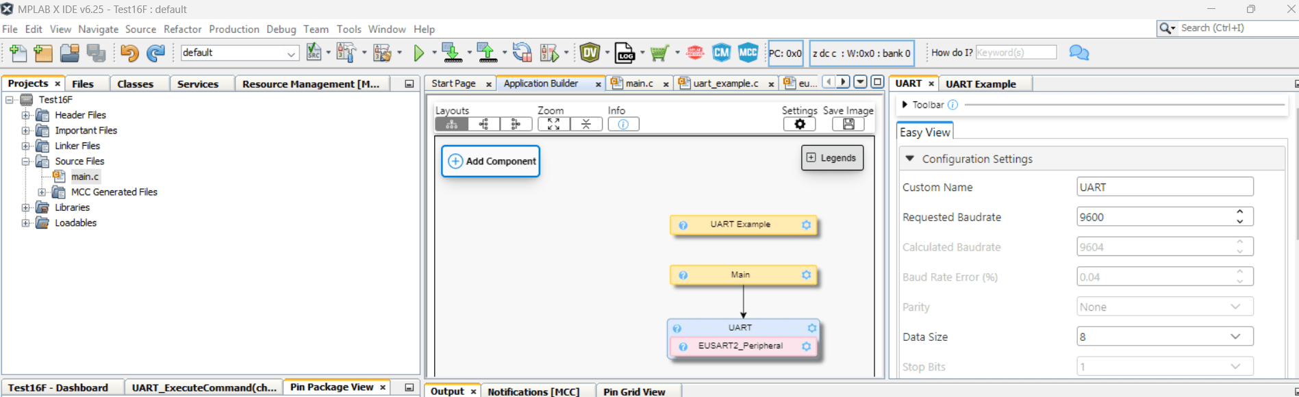
Configurer MPLAB Code Configurator (MCC)
Pour créer le code vous pouvez créer et éditer les fichiers que vous souhaitez ou vous pouvez utiliser l’Application Builder qui vous permet de sélectionner des composants (horloge, timer, bus de communication, etc.), de les paramétrer et de choisir les broches physiques utilisées.


Créer le fichier HEX
Pour créer le fichier HEX que vous pourrez charger dans le PIC, il suffit d’aller dans Production/Build Project ou de cliquer sur l’icône correspondante ou d’appuyer sur F11 (ou MAJ+F11 pour nettoyer)
Le fichier .hex peut se trouver à partir de la racine du projet, dans le dossier production \dist\default\production
Téléverser HEX file dans le PIC
Pour téléverser le programme compilé dans le microcontrôleur nous utilisons l’outil IPE. Après avoir sélectionné le type de MCU et le fichier .hex désiré, nous pouvons programmer le PIC.

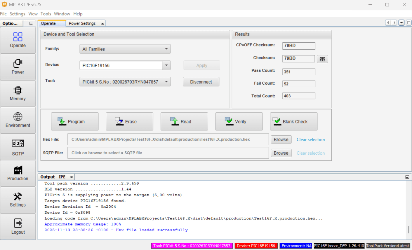
Si cela ne fonctionne pas, vous pouvez:
- Vérifier le branchement du PicKit
- Vérifier l’alimentation du PIC
- Effacer le code en mémoire
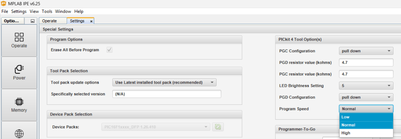
- Changer la vitesse de programmation
Dans Settings/Advance Mode, un mot de passe vous sera demandé (microchip). Dans l’onglet Tool otpion, sélectionné la vitesse de programmation désiré

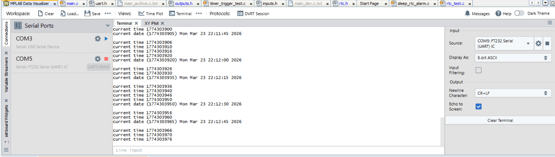
Communication Série
Pour analyser votre code, si vous avez configurer une communication série sur un module TTL-to-USB vous pouvez utiliser le terminal intégré à MPLAB, MPLAB Data Visualizer

Annexe : Charger un programme avec PicKit2
- Installer l’utilitaire PICkit2 v2.61
- Installer dotnet x86