In this series of tutorials, we will see how to drive a multitude of relays with a NodeMCU32S microcontroller and 74HC595 shift registers. We will then see how to address each relay individually. Finally, we will create a web interface to control each relay via the internet. This project is a good basis to develop a home automation system for your home.
This tutorial can be applied to any microcontroller. You will need to be careful to modify the connection diagram and code to suit your use.
Material
- NodeMCU 32S
- Breadboard
- Jumper cable
- 8 relay module
- Shift register 74hc595
Principle
To control the 8 relay module, 8 digital outputs of the microcontroller must be reserved. In order to save the number of inputs/outputs of the microcontroller, different integrated circuits can be used. In particular, the shift register. The shift register 74HC595 has 8 programmable outputs, which can be set to 0 or 5V and only requires 3 digital inputs. This solution is therefore ideal to allow us to control the relays and keep the microcontroller outputs for other functions.
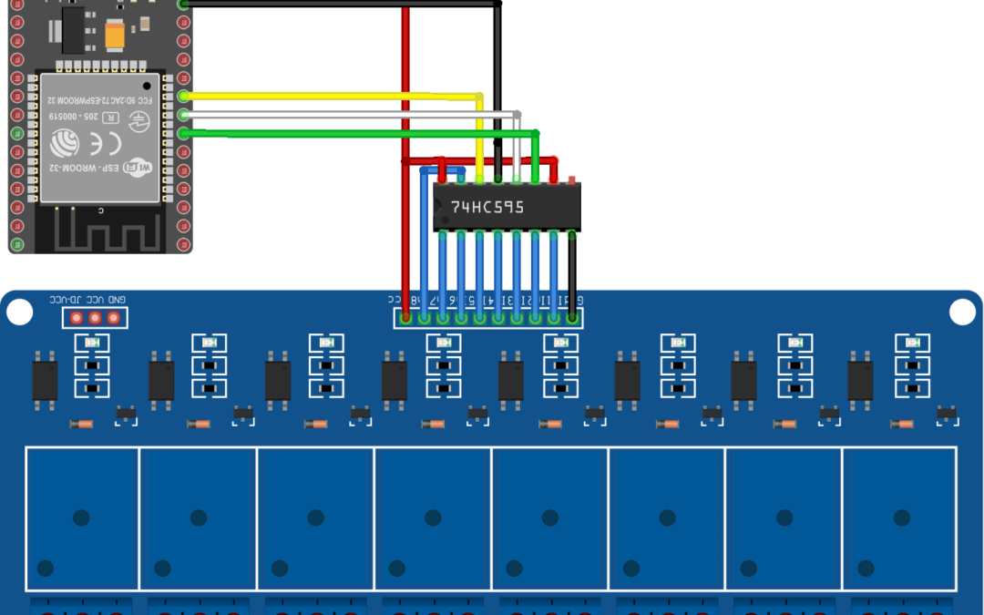
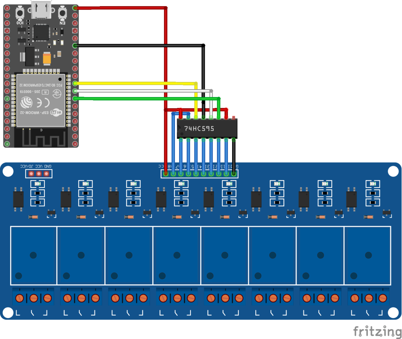
Schematic
To control the shift register, the NodeMCU is connected as follows:
- GND integrated circuit ground
- Vcc power supply pin. Usually connected to 5V
- SH_CP or RCLK connected to pin 33
- ST_CP or SRCLK connected to pin 32
- DS or SER connected to pin 25
The outputs of the integrated circuit 74HC595 (Q0-Q7) are directly connected to the inputs of the 8 relay module. In this tutorial we do not use the Enable (OE) and Reset (MR) pins.
- OE Output enable, activates LOW. Pin connected to GND to activate the outputs.
- MR Master reset, active LOW. Reset pin. Connected to 5V
Attention: The outputs of a microcontroller are current limited. To drive so many relays, it is strongly recommended to use an external voltage source.
Code
In the following code, we will first define the basic functions to manage the shift register. Then we will operate the relays one by one using a for loop.
//Constants
#define number_of_74hc595s 1
#define numOfRegisterPins number_of_74hc595s * 8
#define SER_Pin 25
#define RCLK_Pin 33
#define SRCLK_Pin 32

//Variables
boolean registers [numOfRegisterPins];

void setup(){
//Init Serial USB
Serial.begin(115200);
Serial.println(F("Initialize System"));
//Init register
pinMode(SER_Pin, OUTPUT);
pinMode(RCLK_Pin, OUTPUT);
pinMode(SRCLK_Pin, OUTPUT);
clearRegisters();
writeRegisters();
delay(500);
}

void loop(){
writeGrpRelay();
}

void clearRegisters(){/* function clearRegisters */
//// Clear registers variables
for(int i = numOfRegisterPins-1; i >=  0; i--){
  registers[i] = HIGH;//LOW;
}}

void writeRegisters(){/* function writeRegisters */
//// Write register after being set
digitalWrite(RCLK_Pin, LOW);
 for(int i = numOfRegisterPins-1; i >=  0; i--){
  digitalWrite(SRCLK_Pin, LOW); int val = registers[i];
  digitalWrite(SER_Pin, val);
  digitalWrite(SRCLK_Pin, HIGH);
}
  digitalWrite(RCLK_Pin, HIGH);
}

void setRegisterPin(int index,int value){/* function setRegisterPin */
////Set register variable to HIGH or LOW
registers[index] = value;
}

void writeGrpRelay(){/* function writeGrpRelay */
for(int i = numOfRegisterPins-1; i >=  0; i--){
   Serial.print(F("Relay "));Serial.print(i);Serial.println(F(" HIGH"));
   setRegisterPin(i, LOW);
   writeRegisters();
   delay(200);
   Serial.print(F("Relay "));Serial.print(i);Serial.println(F(" LOW"));
   setRegisterPin(i, HIGH);
   writeRegisters();
  delay(500);

}
}
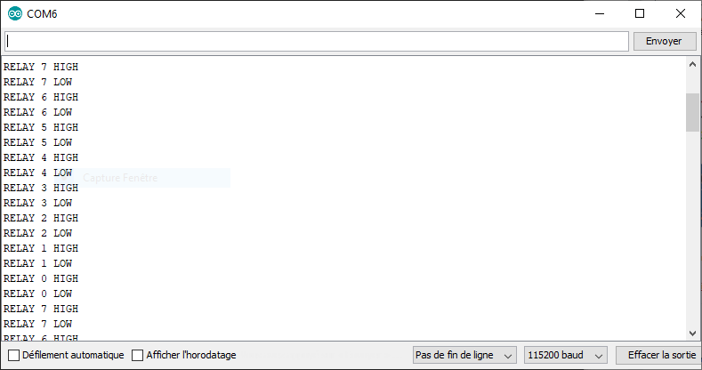
Results
Once the components have been correctly connected and the code loaded into the microcontroller, the relays should activate one after the other.
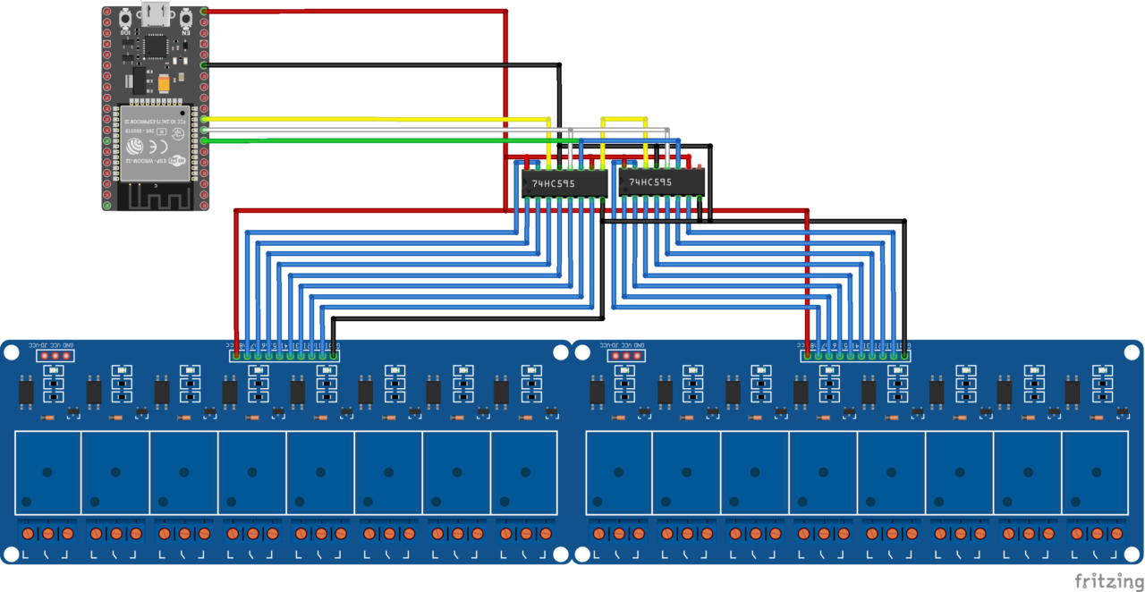
Bonus: Control 16 relays with two shift registers.
Schematic
Code
The beauty of this code is that to make it work with a second shift register you only need to change the parameter:
#define number_of_74hc595s 2
Results


Thanks for the tutorial.
“and only requires 3 digital outputs” – You probably wanted to write “and only requires 3 digital inputs”
Thanks for your comment. You’re absolutely right.
In fact, I meant it uses only 3 I/O (inputs/outputs) of the microcontroller.
Thanks for the education. I am feeding the 16 channel relay from a separate source (5v 2a), but when the arduino power is not connected, when I give electricity to the relay from the 5v adapter, they all light up. Why does it do this?
Hi, are the GND of the external source and Arduino correctly connected? There could be an issue with your wire as well
Some relays board are active when sending LOW.
What do you mean when you send 5V to the relay? You’re feeding one channel with 5V directly?
sharing the same power source but it flickering at the start.
hello, I like your project very much, but can I control each relay high or low one by one?
Of course you can.
Here you have the base code to activate the relays one by one.
You just need to modify the code and call this function with the proper STATE value
setRegisterPin(i, STATE);
writeRegisters();
Good job man. Thanks for sharing your project. I am planning to build a huge 7-segment display scoring system, and I’ll be using an ESP for this one. Your code is a huge help. I would just like to take my time to once again thank you and appreciate your effort!
Thanks a lot for your comment!
I wish you the best for your project
hola
queria saber como modificar este circuito para controlar electrovalvulas en columnas y formar letras o simbolos
graciass
saludos
omar
Good job man. Thanks for sharing your project.i’m very proud to have entered this wonderful website… I have a request… can you add manual control in the same way…
Hello,
I am using your code, but it work just 1 times, then not working
What is my problem, Can you help me, please?
Hello,
What is the serial output? Did you change the code?
thanks again for the code. I just want to turn on n relays and leave them on. Do I even need the loop or can I just do this in the setup?
Yes, sure. Anything is possible
thanks. I added
#define numOfRelays 4
and changed the function in the loop to
void writeGrpRelay(){/* function writeGrpRelay */
for(int i = numOfRelays-1; i >= 0; i–){
Serial.print(F(“Relay “));Serial.print(i);Serial.println(F(” HIGH”));
setRegisterPin(i, LOW);
writeRegisters();
delay(1000);
The serial monitor prints the first 4 relays going high, but in fact all of my relays turn on, not just the first four. What am I doing wrong?
You need to define all the states of the registers (8) even if you only need four.
for(int i = numOfRegisterPins-1; i >= 0; i–){
if (i
Thanks for that hint. I tried this, but I still do not get just four relays to activate.
void writeGrpRelay(){/* function writeGrpRelay */
for(int i = numOfRegisterPins-1; i >= 0; i–){
if (i < numOfRelays ){
setRegisterPin(i, LOW);
Serial.print(F("Relay "));Serial.print(i);Serial.println(F(" HIGH"));
} else {
setRegisterPin(i, HIGH);
Serial.print(F("Relay "));Serial.print(i);Serial.println(F(" LOW"));
}
writeRegisters();
delay(500);
This code should work. You might have something wrong with wiring.
Does the code of the tutorial work as expected?
yes, the example works. I tried calling writeGrpRelay(); from the loop section like in the example and just after writeRegisters(); in the setup section (deleting that line in the loop). Either all of the relays come on or they all stay off.
The only other change was the pins to the following, but the example worked with this:
#define SER_Pin 15
#define RCLK_Pin 13
#define SRCLK_Pin 4
correction: The example is giving me strange results. It like they are turning on one by one but skipping the turn off part of the writeGrpRelay function. As they turn on one by one they turn off the previous one, but the function gets out of synch because it is printing something that does not correspond to what is happening.
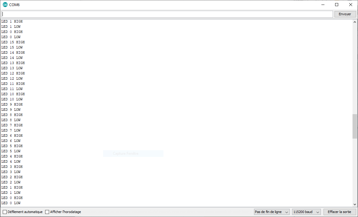
Here are the results I am seeing (using an LED instead of a relay):
Serial Print LED activity
Relay 0 HIGH nothing
Relay 0 LOW LED 0 turns on
Relay 7 HIGH 0 turns off, 7 turns on
Relay 7 LOW 7 turns off, 6 turns on
Relay 6 HIGH 6 turns off, 5 turns on
Relay 6 LOW 5 turns off, 4 turns on
Relay 5 HIGH 4 turns off, 3 turns on
Relay 5 LOW 3 turns off, 2 turns on
Relay 4 HIGH 2 turns off, 1 turns on
Relay 4 LOW 1 turns off
Relay 3 HIGH nothing
Relay 3 LOW nothing
Relay 2 HIGH nothing
Relay 2 LOW nothing
Relay 1 HIGH nothing
Relay 1 LOW nothing