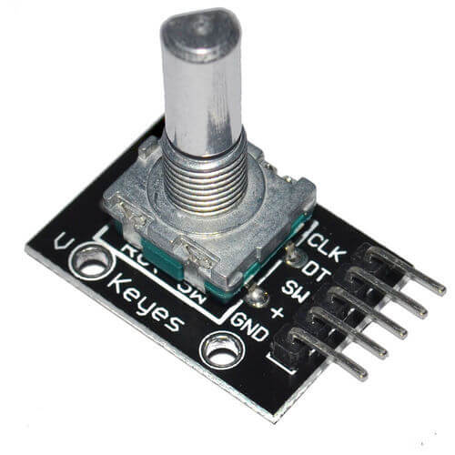
The rotary encoder is a rotation sensor whose direction and angle can be known. Similar in appearance to the potentiometer, the encoder has no limit stroke and instead of returning a resistance value, like the potentiometer, the encoder returns two digital signals representing direction and rotation.
With the appropriate algorithm, it is possible to recover the state of these two contactors and to find their position again. The rotary encoder is sometimes coupled with a push button which is useful when you want to create an interface.

Hardware
- Computer
- Arduino UNO
- USB cable A Male to B Male
- Rotary encoder
Principle of operation
The rotary encoder is equipped with two contactors, one which closes or opens depending on the direction of rotation; the other opens and closes when the encoder shaft is rotated. Knowing this, an encoder sends two digital signals (UP or DOWN state), one to recover the direction and the other to measure the angle of rotation. The number of state changes over one revolution varies according to the resolution of the potentiometer.
Schematic
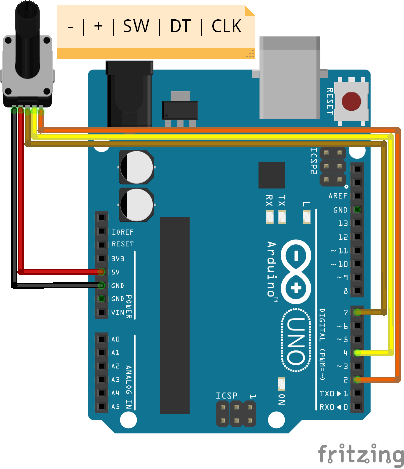
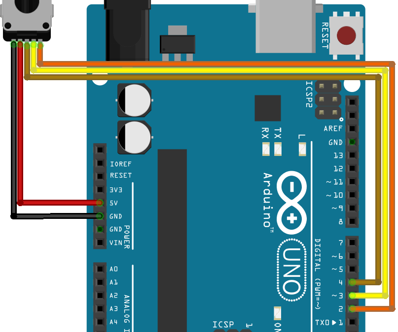
A sensor that returns a digital signal is preferably connected to the digital inputs of the microcontroller. The rotary encoder has 3 output pins: one for the push button (SW) and two for direction (DT) and rotation detection (CLK).

Code
To retrieve the information from the rotary encoder, we will need to track the changes of state of each output signal from the sensor and define the variables and their changes based on these signals. Specifically, the algorithm detects when the spindle changes from UP to DOWN state. Then we detect the direction of rotation by testing whether the DT spindle is in the UP or DOWN state, if the direction of rotation is counterclockwise the variable rotVal is decremented otherwise it is incremented.
//Parameters
const int clkPin  = 2;
const int dtPin  = 4;
const int swPin  = 7;

//Variables
int rotVal  = 0;
bool clkState  = LOW;
bool clkLast  = HIGH;
bool swState  = HIGH;
bool swLast  = HIGH;

void setup() {
  //Init Serial USB
  Serial.begin(9600);
  Serial.println(F("Initialize System"));
  //Init Rotary
  pinMode(clkPin,INPUT);
  pinMode(dtPin,INPUT);
  pinMode(swPin,INPUT_PULLUP);
}

void loop() {
  readRotary();
}

void readRotary( ) { /* function readRotary */
  ////Test routine for Rotary
  // gestion position
  clkState = digitalRead(clkPin);
  if ((clkLast == LOW) && (clkState == HIGH)) {//rotary moving
    Serial.print("Rotary position ");
    if (digitalRead(dtPin) == HIGH) {
      rotVal = rotVal - 1;
      if ( rotVal < 0 ) {
        rotVal = 0;
      }
    }
    else {
      rotVal++;
      if ( rotVal > 10 ) {
        rotVal = 10;
      }
    }
    Serial.println(rotVal);
    delay(200);
  }
  clkLast = clkState;

  //gestion bouton
  swState = digitalRead(swPin);
  if (swState == LOW && swLast == HIGH) {
    Serial.println("Rotary pressed");
    delay(100);//debounce
  }
  swLast = swState;
}
Result
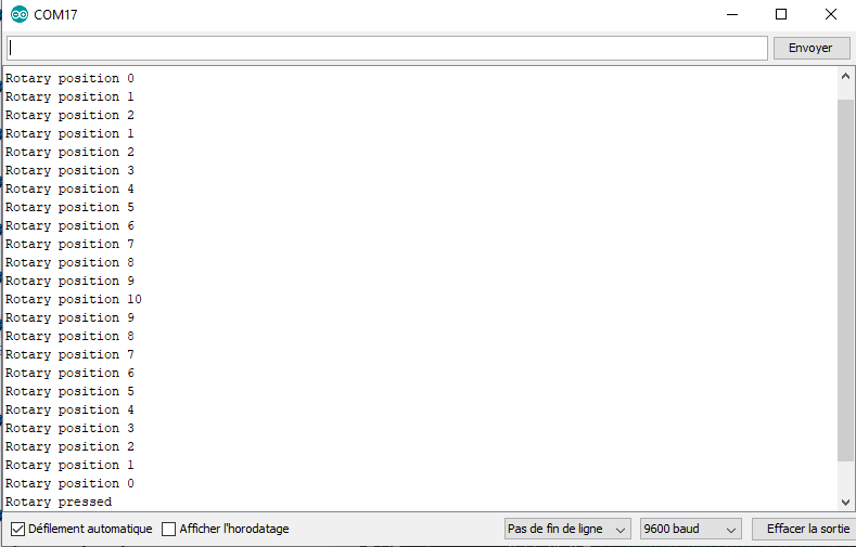
The rotVal variable is observed to change as the encoder rotates and the pressure on the encoder shaft is correctly detected.

Applications
- Replacing a potentiometer and button in an interface with a rotary encoder
- Position or speed sensor
Sources
Find other examples and tutorials in our Automatic code generator
Code Architect
