In this tutorial we will see the use of the CNC Shield V3 for Arduino. To be able to manage a machine like a CNC or a 3D printer with several stepper motors, it is interesting to have a board that facilitates the connection of the different elements of the machine. This is the role of the CNC shield.
Material
- Arduino UNO
- CNC Shield V3
- Stepper driver A4988 or DRV8825 or SilentStepStick
- USBA male to USB B male cable
Principle of operation
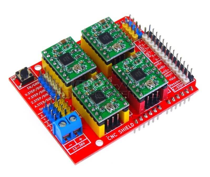
The CNC Shield V3 is an extension board for Arduino UNO or Mega allowing to interface easily to stepper motor controllers, type A4988. It also allows to drive and manage the elements necessary to operate a digital milling machine (CNC). That is, end stops, fan, etc,
Scheme
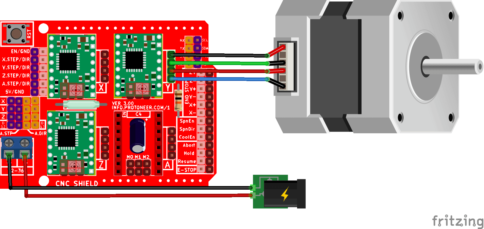
The Shield is placed on the Arduino microcontroller and the motors are connected directly to the output pins of the drivers. You can choose the drivers you want depending on the power of your motors and your applications (A4988, DRV8825, SilentStepStick, TMC).
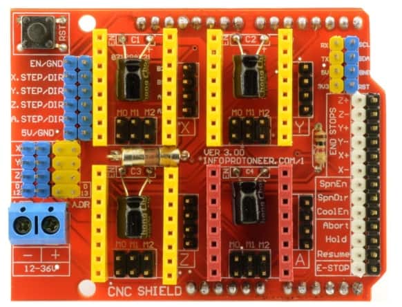
Terminals are available below each driver to select the step resolution. These terminals are connected to the MS0, MS1 and MS2 pins of the controllers.
Before connecting the motors, be sure to set the current limiter on each controller to match the motor it is driving.
Code
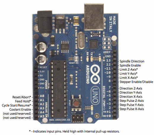
To drive a stepper motor with CNC Shield V3, we refer to the pinout of the shield which gives us access to the pins to call to send commands to the motor controller (DRV8825, A4988 or SilentStepStick).
const int enPin=8;
const int stepXPin = 2; //X.STEP
const int dirXPin = 5; // X.DIR
const int stepYPin = 3; //Y.STEP
const int dirYPin = 6; // Y.DIR
const int stepZPin = 4; //Z.STEP
const int dirZPin = 7; // Z.DIR

int stepPin=stepYPin;
int dirPin=dirYPin;

const int stepsPerRev=200;
int pulseWidthMicros = 100;  // microseconds
int millisBtwnSteps = 1000;

void setup() {
  Serial.begin(9600);
  pinMode(enPin, OUTPUT);
  digitalWrite(enPin, LOW);
  pinMode(stepPin, OUTPUT);
  pinMode(dirPin, OUTPUT);

  Serial.println(F("CNC Shield Initialized"));
}

void loop() {
  Serial.println(F("Running clockwise"));
  digitalWrite(dirPin, HIGH); // Enables the motor to move in a particular direction
  // Makes 200 pulses for making one full cycle rotation
  for (int i = 0; i < stepsPerRev; i++) {
    digitalWrite(stepPin, HIGH);
    delayMicroseconds(pulseWidthMicros);
    digitalWrite(stepPin, LOW);
    delayMicroseconds(millisBtwnSteps);
  }
  delay(1000); // One second delay

  Serial.println(F("Running counter-clockwise"));
  digitalWrite(dirPin, LOW); //Changes the rotations direction
  // Makes 400 pulses for making two full cycle rotation
  for (int i = 0; i < 2*stepsPerRev; i++) {
    digitalWrite(stepPin, HIGH);
    delayMicroseconds(pulseWidthMicros);
    digitalWrite(stepPin, LOW);
    delayMicroseconds(millisBtwnSteps);
  }
  delay(1000);
}
To test the operation of the Shield and the engines, we do not use any particular library. Note however, that if you want to use more advanced features you can use the AccelStepper library or the GRBL V0.9 firmware.
Result
Once the code is uploaded and the system is plugged in, you should see the motor connected to the Y driver turn one turn clockwise and two turns counterclockwise. If this is not the case, you probably have a connection problem.
It is also possible that the fuse on the board is damaged. You can replace it with a conductive wire.
Applications
- Build your own CNC or laser engraver
- Make a cutter
- Drive up to three stepper motors independently


What about the enable pin on the shield? Some say to ground it, others don’t talk about it, and your sketch shows enable is software controlled.
the enable pin is used to enable/disable stepper motors. It is enabled at LOW. You can permanently enable the stepper by grounding the pin.
You can leave it free if you are confident that no parasitic signal will disturb the state of the pin
What power source would you recommend to use?
It depends on your stepper motor and laser or driller.
switching power supply 12V or 24V with 10A or more
https://fr.rs-online.com/web/p/alimentations-a-decoupage/1618228?gb=s