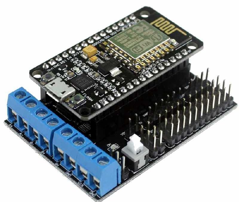
The ESP12E Motor Shield is an expansion board that allows an Amica ESP8266 NodeMCU (V2) to drive two DC motors or one stepper motor. We have seen how to drive a DC motor using an H-bridge which can require a lot of wiring when using the simple IC. For an embedded application, like a Willy robot, you will have to drive several motors in parallel. There are Shields for this purpose which will simplify the assembly.
Material
- Computer
- NodeMCU ESP8266 Amica (V2)
- USB cable A Male/B Male
- Blindage moteur ESP12E
- DC motor x2 or Stepper motor x1
Principle of operation
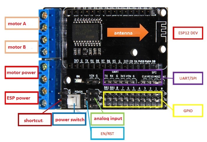
The ESP12E Motor Shield uses the L293D double H-bridge. It allows to drive motors in direction and speed with a nominal voltage between 5 and 36V and a current of 600mA, up to 1.2A with an external voltage source:
This shield allows you to use:
- up to two DC motors or one bipolar stepper motor
- an analog sensor
- GPIOs
- I2C, SPI and UART buses
Scheme
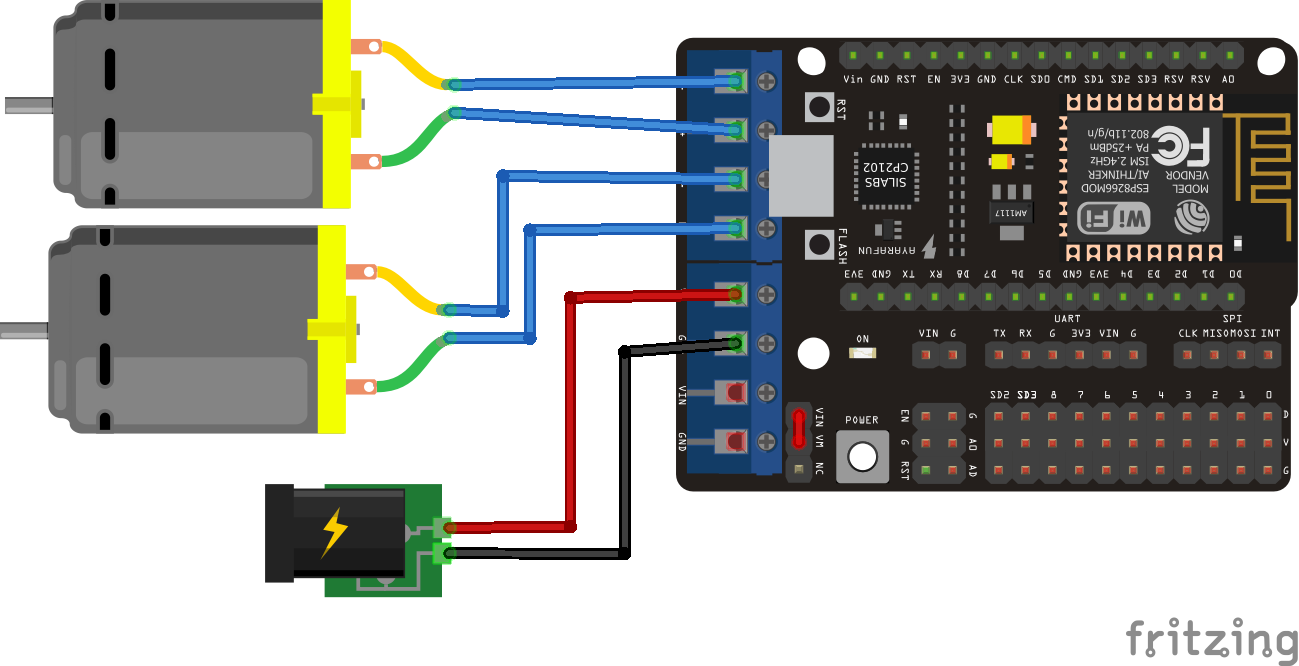
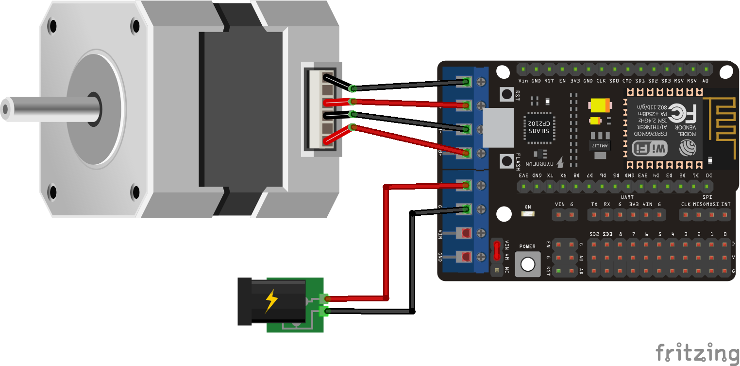
Compatible with the NodeMCU ESP8266 Amica board, the shield is placed directly on the microcontroller. The power supply of the motors is connected to the VM/GND terminal block and that of the board to the VIN/GND terminal block. It is possible to connect the VIN and VM pins with a bridge, if the power supply of the motors is the same as the power supply of the NodeMCU (<10V Max). The motors are connected to the terminal blocks A+,A-,B+,B-.
- D1, D3 (motor A/ Stepper 1,2)
- D2, D4 (motor B / Stepper 3,4)
- Available input A0
- GPIO disponibles sur les broches 0 à 8
In the case of a shield, the connections are predefined. Check the technical documentation of the component to see how to use it.
The motor connections are detailed in the following diagrams.
Management code for a DC motor
To interact with the ESP12E Motor Shield, we don’t use a specific library. You can always create your own library to simplify your code.
/*
   Board pin | NodeMCU GPIO |  Arduino IDE
      A-           1             5 or D1
      A+           3             0 or D3
      B-           2             4 or D2
      B+           4             2 or D4
*/

const int pwmMotorA = D1;
const int pwmMotorB = D2;
const int dirMotorA = D3;
const int dirMotorB = D4;

int motorSpeed = 500;

void setup() {
  Serial.begin(115200);
  Serial.println();

  pinMode(pwmMotorA , OUTPUT);
  pinMode(pwmMotorB, OUTPUT);
  pinMode(dirMotorA, OUTPUT);
  pinMode(dirMotorB, OUTPUT);

  Serial.println("Motor SHield 12E Initialized");
  delay(5000);
}

void loop() {
  Serial.println("Activate A");
  digitalWrite(pwmMotorA, motorSpeed);
  digitalWrite(dirMotorA, LOW);
  delay(1500);

  Serial.println("Reverse A");
  digitalWrite(dirMotorA, HIGH);
  delay(1500);

  Serial.println("Stop A");
  digitalWrite(pwmMotorA, 0);
  digitalWrite(dirMotorA, LOW);
  delay(3000);

  Serial.println("Activate B");
  digitalWrite(pwmMotorB, motorSpeed);
  digitalWrite(dirMotorB, LOW);
  delay(1500);

  Serial.println("Reverse B");
  digitalWrite(dirMotorB, HIGH);
  delay(1500);

  Serial.println("Stop B");
  digitalWrite(pwmMotorB, 0);
  digitalWrite(dirMotorB, LOW);
  delay(3000);
}
Stepper motor management code
To drive a stepper motor, the motor coils must be activated in a precise sequence. This sequence is described in the nextStep() function.
const int pwmMotorA = D1;
const int pwmMotorB = D2;
const int dirMotorA = D3;
const int dirMotorB = D4;

int delayBtwnStep = 3;

void setup() {
  Serial.begin ( 115200 );
  Serial.println();

  pinMode(pwmMotorA, OUTPUT);
  pinMode(pwmMotorB, OUTPUT);
  pinMode(dirMotorA, OUTPUT);
  pinMode(dirMotorB, OUTPUT);
  Serial.println("Motor SHield 12E Initialized");
}

void loop() {
  stepperRotate(10, 0);
  delay(500);
  stepperRotate(10, 1);
  delay(500);
}


void stepperRotate(int nbStep, int dirStep) {
  for (int i = 0; i <= nbStep; i++) {
    if (dirStep == 0) {  // sens horaire
      nextStep(i % 4);
    }
    if (dirStep == 1) {  // sens antihoraire
      nextStep(3 - (i % 4));
    }
    delay(delayBtwnStep);
  }
}


void nextStep(int index) {
  if (index == 0) {
    digitalWrite(pwmMotorA, true);
    digitalWrite(pwmMotorB, false);
    digitalWrite(dirMotorA, true);
    digitalWrite(dirMotorB, false);
  }
  if (index == 1) {
    digitalWrite(pwmMotorA, false);
    digitalWrite(pwmMotorB, true);
    digitalWrite(dirMotorA, true);
    digitalWrite(dirMotorB, false);
  }
  if (index == 2) {
    digitalWrite(pwmMotorA, false);
    digitalWrite(pwmMotorB, true);
    digitalWrite(dirMotorA, false);
    digitalWrite(dirMotorB, true);
  }
  if (index == 3) {
    digitalWrite(pwmMotorA, true);
    digitalWrite(pwmMotorB, false);
    digitalWrite(dirMotorA, false);
    digitalWrite(dirMotorB, true);
  }
}
Applications
- Controlling a two-wheeled robot like Willy via a WiFi connection
Sources
Retrouvez nos tutoriels et d’autres exemples dans notre générateur automatique de code
La Programmerie


Thanks for the guide, but sadly the stepper motor code you provided did not work for me. After a lot of debugging, the following pin assignment made it work:
const int pwmMotorA = D1;
const int pwmMotorB = D2;
const int dirMotorA = D4;
const int dirMotorB = D3;
Also, if anyone is interested, here is some code to do half stepping:
static uint8 current_phase = 0;
void stepperRotate(int nbStep, int dirStep) {
for (int i = 0; i <= nbStep; i++) {
if (dirStep == 0) { // clockwise
current_phase = (current_phase + 1) % 8;
}
if (dirStep == 1) { // anticlockwise
current_phase = (current_phase + 7) % 8; // +7 mod 8 is the same as -1 mod 8
}
nextStep(current_phase);
delay(delayBtwnStep);
}
}
void nextStep(int index) {
if (index == 0) {
digitalWrite(pwmMotorA, true);
digitalWrite(pwmMotorB, false);
digitalWrite(dirMotorA, true);
digitalWrite(dirMotorB, true);
}
if (index == 1) {
digitalWrite(pwmMotorA, true);
digitalWrite(pwmMotorB, true);
digitalWrite(dirMotorA, true);
digitalWrite(dirMotorB, true);
}
if (index == 2) {
digitalWrite(pwmMotorA, false);
digitalWrite(pwmMotorB, true);
digitalWrite(dirMotorA, true);
digitalWrite(dirMotorB, true);
}
if (index == 3) {
digitalWrite(pwmMotorA, true);
digitalWrite(pwmMotorB, true);
digitalWrite(dirMotorA, false);
digitalWrite(dirMotorB, true);
}
if (index == 4) {
digitalWrite(pwmMotorA, true);
digitalWrite(pwmMotorB, false);
digitalWrite(dirMotorA, false);
digitalWrite(dirMotorB, false);
}
if (index == 5) {
digitalWrite(pwmMotorA, true);
digitalWrite(pwmMotorB, true);
digitalWrite(dirMotorA, false);
digitalWrite(dirMotorB, false);
}
if (index == 6) {
digitalWrite(pwmMotorA, false);
digitalWrite(pwmMotorB, true);
digitalWrite(dirMotorA, false);
digitalWrite(dirMotorB, false);
}
if (index == 7) {
digitalWrite(pwmMotorA, true);
digitalWrite(pwmMotorB, true);
digitalWrite(dirMotorA, true);
digitalWrite(dirMotorB, false);
}
}