In this tutorial, we’ll look at how to configure the GRBL 0.9 firmware for Ramps 1.4 with Arduino Mega 2560 and interface with LaserGRBL. To control your CNC or MPCNC with LaserGRBL, you need to install and configure firmware on your Arduino board, so that it can correctly interpret the commands from your engraving software.
This tutorial follows this one: Installation and wiring of a Ramps 1.4 card for an MPCNC.
Hardware
- Arduino MEGA 2560
- RAMPS 1.4 card
- 1 Laser 20W: LD4070HA
- 5 Stepper motors: 17HS15-1504S-X1
- 3 Stepper motor drivers: DRV8825
Software
Cleaning the EEPROM
Before downloading and uploading GRBL to your card, you need to ensure that all stored values are cleaned, and to do this you need the following code to reset your card to default settings:
/*
 * EEPROM Clear
 *
 * Sets all of the bytes of the EEPROM to 0.
 * Please see eeprom_iteration for a more in depth
 * look at how to traverse the EEPROM.
 *
 * This example code is in the public domain.
 */

#include <EEPROM.h>

void setup() {
  // initialize the LED pin as an output.
  pinMode(13, OUTPUT);

  /***
    Iterate through each byte of the EEPROM storage.
    Larger AVR processors have larger EEPROM sizes, E.g:
    - Arduino Duemilanove: 512 B EEPROM storage.
    - Arduino Uno:         1 kB EEPROM storage.
    - Arduino Mega:        4 kB EEPROM storage.
    Rather than hard-coding the length, you should use the pre-provided length function.
    This will make your code portable to all AVR processors.
  ***/

  for (int i = 0 ; i < EEPROM.length() ; i++) {
    EEPROM.write(i, 0);
  }

  // turn the LED on when we're done
  digitalWrite(13, HIGH);
}

void loop() {
  /** Empty loop. **/
}
Connect your Arduino board to the serial port with its USB cable, copy and paste this code into your Arduino IDE and then upload to clean the EEPROM.
Modifying GRBL for Ramps
You can download GRBL for Ramps from this Github Repository. If you don’t know how to use Git, you can follow this tutorial to learn the basics.
The GRBL firmware has been modified in some places to suit our MPCNC. Before uploading the Firmware with Arduino IDE, here are the parameters to check in relation to your installation:
// Enables variable spindle output voltage for different RPM values. On the Arduino Uno, the spindle
// enable pin will output 5V for maximum RPM with 256 intermediate levels and 0V when disabled.
// NOTE: IMPORTANT for Arduino Unos! When enabled, the Z-limit pin D11 and spindle enable pin D12 switch!
// The hardware PWM output on pin D11 is required for variable spindle output voltages.
#define VARIABLE_SPINDLE // Default disabled. Uncomment to enable.<----------------------------------- Uncommented for Ramps 1.4
Here, we uncomment the #define VARIABLE_SPINDLE line in the config.h file to enable PWM control of the laser.
/*-----------------------------------------------------------suite du code---------------------------------------------------*/
// Define spindle enable and spindle direction output pins.
#define SPINDLE_ENABLE_DDR   DDRH
#define SPINDLE_ENABLE_PORT  PORTH
#define SPINDLE_ENABLE_BIT   6  // MEGA2560 Digital Pin 9 <---------- Modified for Ramps 1.4. Orignal was BIT 3 for Digital Pin 6
#define SPINDLE_DIRECTION_DDR   DDRE
#define SPINDLE_DIRECTION_PORT  PORTE
#define SPINDLE_DIRECTION_BIT   3 // MEGA2560 Digital Pin 5

// Define flood and mist coolant enable output pins.
// NOTE: Uno analog pins 4 and 5 are reserved for an i2c interface, and may be installed at
// a later date if flash and memory space allows.
#define COOLANT_FLOOD_DDR   DDRH
#define COOLANT_FLOOD_PORT  PORTH
#define COOLANT_FLOOD_BIT   5 // MEGA2560 Digital Pin 8
#ifdef ENABLE_M7 // Mist coolant disabled by default. See config.h to enable/disable.
#define COOLANT_MIST_DDR   DDRH
#define COOLANT_MIST_PORT  PORTH
#define COOLANT_MIST_BIT   3 // MEGA2560 Digital Pin 6 <---------- Modified for Ramps 1.4. Orignal was BIT 6 for Digital pin 9
/*-----------------------------------------------------------suite du code--------------------------------------------------*/
Here, in the file entitled cpu_map.h, you need to pay close attention to the output pins for the “Spindle”, which correspond to the pin for activating or deactivating the Laser.
#define SPINDLE_PWM_DDR		DDRB // <------------------------------ Modified for Ramps 1.4. Orignal was DDRH
#define SPINDLE_PWM_PORT    PORTB // <--------------------------- Modified for Ramps 1.4. Orignal was PORTH
#define SPINDLE_PWM_BIT		5 // MEGA2560 Digital Pin 11 <--------- Modified for Ramps 1.4. Orignal was BIT 6 for Digital Pin 9
#endif // End of VARIABLE_SPINDLE
Pinout configuration
Still in the same file, cpu_map.h, we modify the PWM laser power control pin to match our wiring.
To understand these modifications, we need to look at the structural diagrams of the Ramps 1.4 board and the Arduino MEGA 2560 :
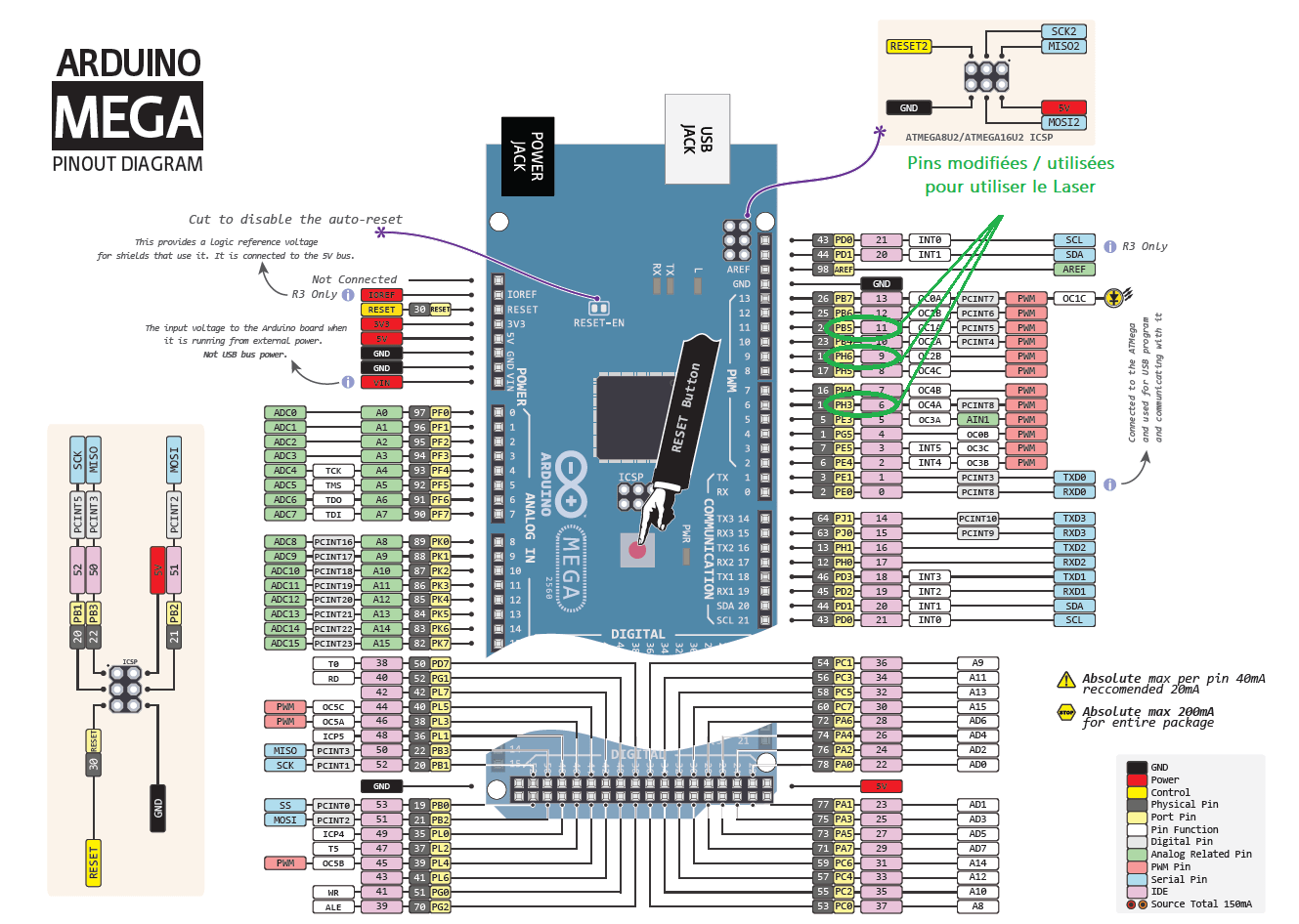
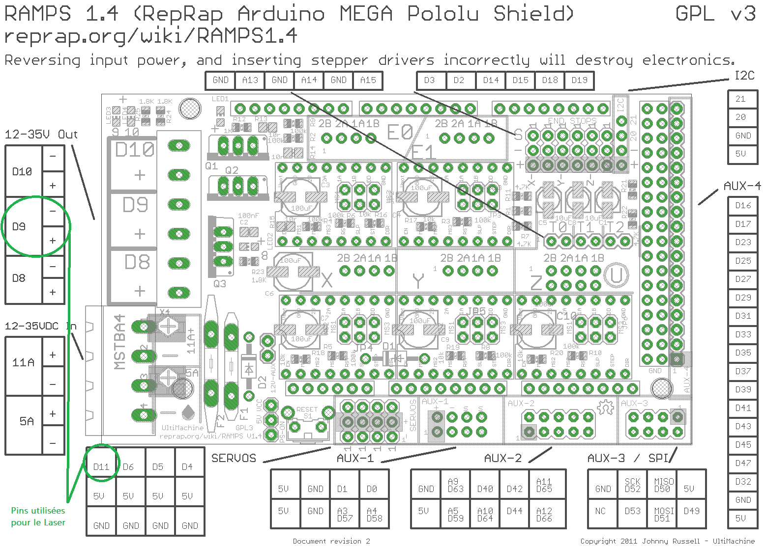
Note that the digital pins we use to power the laser (Pin Digital 9) and the one we use to control it (Pin Digital 11) are defined through their PORT, hence the need to define them by their Port numbers, respectively 6 on the PORTH and 5 on the PORTE (PH6 and PE5 on the diagram).the PH3 modification for pin digital 6 is just to free pin digital 9, which is used as the base for a cooling system that is not in our configuration.
Now that you’ve understood the changes made to the firmware, you can upload it to your Arduino board. Please note that it may take several minutes to compile, so please be patient.
GRBL configuration menu
Once LaserGRBL has been installed, open the application and connect via USB to your Arduino Mega board.
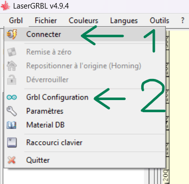
Next, click on Grbl Configuration, which corresponds to the parameters specific to the connected CNC. You can only modify and rewrite values when LaserGRBL is connected to your CNC.
You’ll have access to your CNC parameters, which will be saved on your Arduino board.
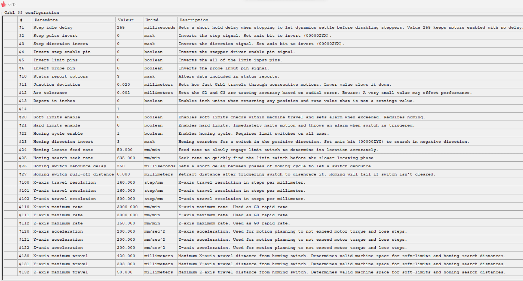
N.B.: if you use several machines or computers, you can export and import your configuration settings.
Deactivation of position limits
First of all, disable Soft Limits by setting the value of the Soft limits enable line to 0 (&20 and $21). This will make the first tests easier without LaserGRBL thinking that your machine is outside its dimensions.

Parameter settings
The important parameters here are all those relating to the X, Y and Z axes. To set the travel resolution value for each axis, refer to the equation: Travel resolution = (Steps per revolution * Mechanical reduction)
- Steps per revolution: This is the number of steps taken by the motor to complete a full rotation (here 200 steps per revolution).
- Gear reduction: If your system uses gears or pulleys to reduce or increase torque, you need to consider the mechanical reduction ratio. This will affect the effective displacement resolution of the axis. We use belts with a mechanical reduction ratio of 40:1.
- Microstepping: Some stepper motor controllers support microstepping, which divides each electrical step. This provides better resolution. Possible values are 1
For acceleration, please refer to the value given on the motor datasheet.
Notes on parameter calculations
- Resolution
For a pulley (20 tooth) belt (2mm pitch) system with micro-pitch (1
( 200 * 32 )
For a worm gear system with a ratio of 8mm per revolution and microstep (1
( 200 * 32 )
- maximum speed
For the maximum speed, i.e. the Maximum Rate, you can use the following equation:
Maximum speed = (Steps per revolution * Maximum step pulse frequency)
In our caseMaximum speed = ( 200*36,000)
- working area
The maximum travel size depends on the actual working area of your CNC. To measure it :
- First configure the previous parameters
- Using the arrows on the LaserGRBL user interface, move your CNC head to the bottom left-hand corner.
- Switch on the laser with the Focus button and mark the point where it is pointed, for example by switching on the laser with high power.
- repeat the operation in all corners.
- measure the work surface with a ruler or tape measure.
Modifying and adding buttons to LaserGRBL
To modify a button, simply right-click on it and choose “Edit button”.
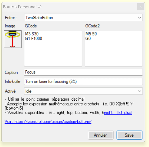
You can change the GCode sent by the button as well. To make the Laser Focus and Blink work at 3% of their power, you can set these GCodes as follows.
; pour GCode
M3 S30
G1 F1000
; pour GCode2
M5 S0
G0
To create your own button, you can right-click on an empty area of the user interface where there is no button and choose “Add a custom button”. This can be useful, for example, to add a Z-axis manipulator if you want to change the height of your CNC tool:
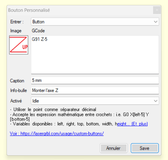
- Enter: allows you to choose whether this is a button that is activated by clicking on it once, by holding it down, that is activated by clicking on it, etc.
- Caption: this will be the name displayed for your button
- Tooltip: describes what your button does
- Activated: lets you know when the button will be unlocked. Here, Idle means it will be active only if the CNC is connected and unlocked.
- GCode: this is where you put the command lines that your button will send to your CNC. Here are different GCodes for 6 buttons to move the Z axis with different precision:
G91 Z-10 ; Monter l'axe Z de 10mm
G91 Z10 ; Descendre l'axe Z de 10mm
G91 Z-5 ; Monter l'axe Z de 5mm
G91 Z5 ; Descendre l'axe Z de 5mm
G91 Z-1 ; Monter l'axe Z de 1mm
G91 Z1 ; Descendre l'axe Z de 1mm
Sources
- https://planet-cnc.com/how-to-setup-cnc/
- https://blog.orientalmotor.com/motor-sizing-basics-part-3-acceleration-torque-and-rms-torque
- https://lasergrbl.com/configuration/
- https://docs.v1e.com/learn/gcode/
- https://www.youtube.com/watch?v=erXw09OcdeU


