In this tutorial, we’ll show you how to drive a bipolar stepper motor using an A4988 driver. This tutorial is compatible with stepper motor drivers commonly used in digital milling or 3D printer projects (DRV8825, SilentStepStick, etc.).
Hardware
- Arduino UNO
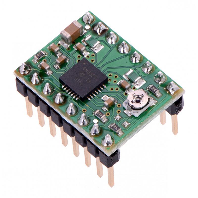
- Stepper driver A4988
- USB A male to USB B male cable
Operating principle
Stepper motor drivers enable efficient motor control using just two control signals, STEP and DIR. The number of pulses sent to the driver corresponds to the number of steps taken, the pulse frequency to the motor speed, and the dir signal to the direction of motor rotation. The A4988 module takes care of sending the sequence to the two motor coils according to the commands received as input.
Technical specifications A4988
| Minimum operating voltage | 8 V |
| Maximum operating voltage | 35 V |
| Continuous current per phase | 1.2 A |
| Maximum current per phase | 2 A |
| Minimum logic voltage | 3 V |
| Maximum logic voltage | 5.5 V |
| Microstep resolution | full, 1/2, 1/4, 1/8 and 1/16 |
| Reverse voltage protection? | No |
| Dimensions | 15.5 × 20.5 mm (0.6″ × 0.8″) |
Diagram
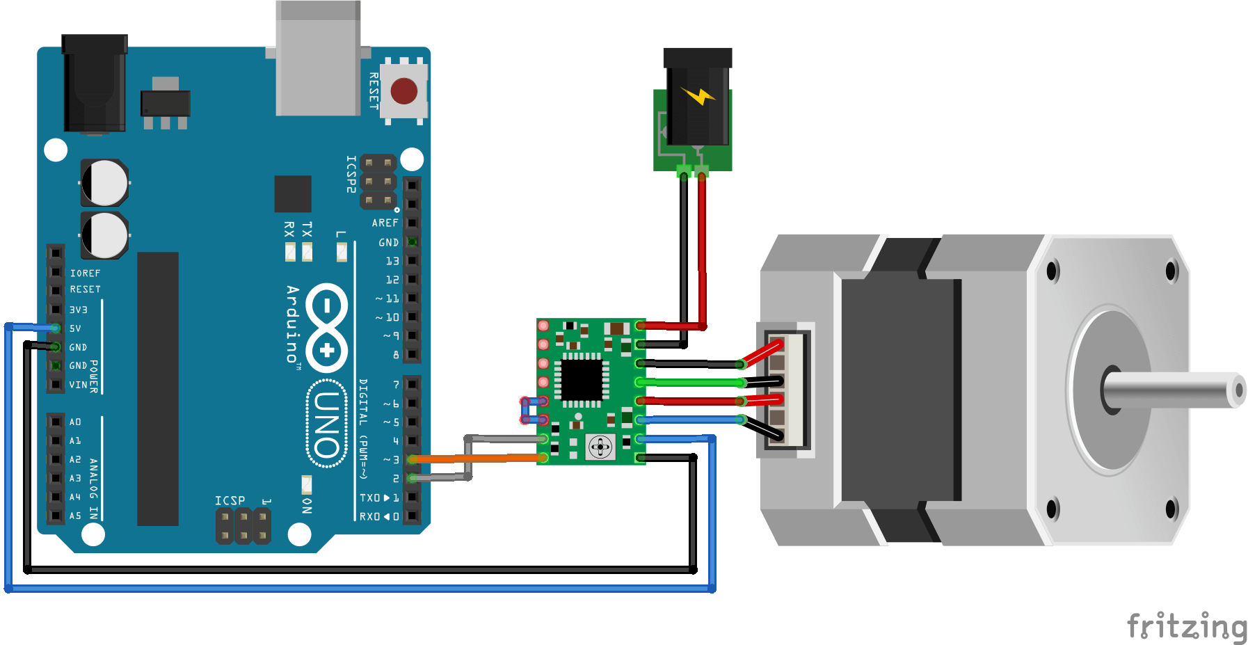
Before connecting your motor to the driver, please set the current limiter correctly. This requires:
- supply the Arduino and Shield with Motor voltage.
- Then place a voltmeter between the potentiometer and GND.
- Turn the potentiometer with a screwdriver until you obtain the value that follows the following rule.
MaxCurrent=Vref x 2.5
For example:
If the current value is 1A, the value displayed on the multimeter must be equal to 0.4V.
MaxCurrent=1.0A –> Vref = 0.4V
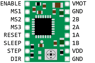
It is possible to modify the driver step resolution for greater precision. This configuration is defined by setting pins M0, M1 and M2 to HIGH or LOW according to the following logic table.
| MS1 | MS2 | MS3 | Résolution Microstepping |
| Low | Low | Low | Pas complet (full step) |
| High | Low | Low | 1/2 pas |
| Low | High | Low | 1/4 de pas |
| High | High | Low | 1/8 ième de pas |
| High | High | High | 1/16 ième de pas |
Code
To drive the stepper motor driver, we simply send a HIGH or LOW state to the DIR pin and a pulse to the STEP pin.
const int stepPin = 2;
const int dirPin = 3;


const int stepsPerRev=200;
int pulseWidthMicros = 100;  // microseconds
int millisBtwnSteps = 1000;

void setup() {
  Serial.begin(9600);
  pinMode(stepPin, OUTPUT);
  pinMode(dirPin, OUTPUT);

  Serial.println(F("A4988 Initialized"));
}

void loop() {
  Serial.println(F("Running clockwise"));
  digitalWrite(dirPin, HIGH); // Enables the motor to move in a particular direction
  // Makes 200 pulses for making one full cycle rotation
  for (int i = 0; i < stepsPerRev; i++) {
    digitalWrite(stepPin, HIGH);
    delayMicroseconds(pulseWidthMicros);
    digitalWrite(stepPin, LOW);
    delayMicroseconds(millisBtwnSteps);
  }
  delay(1000); // One second delay

  Serial.println(F("Running counter-clockwise"));
  digitalWrite(dirPin, LOW); //Changes the rotations direction
  // Makes 400 pulses for making two full cycle rotation
  for (int i = 0; i < 2*stepsPerRev; i++) {
    digitalWrite(stepPin, HIGH);
    delayMicroseconds(pulseWidthMicros);
    digitalWrite(stepPin, LOW);
    delayMicroseconds(millisBtwnSteps);
  }
  delay(1000);
}
For more functionality, you can use the AccelStepper.h library.
Applications
- Stepper motor control
- Controlling multiple motors with a CNC Shield


