It can be practical, especially in home automation projects, to communicate between several devices. One of the commonly used techniques is the I2C (or TWI) protocol. The I2C protocol is a method which makes it possible to connect several “Master” cards and several “Slave” cards and to communicate up to 128 devices. It allows asynchronous connections between several components to share information via a “common bus”. We had seen the communication via the Serial port (called UART) which is used to send the code to the Arduino by a computer or to connect two devices in particular in Bluetooth.
Equipment
- Computer
- Arduino UNO x2 or more
- Jumper cable M / M x3 times the number of cards
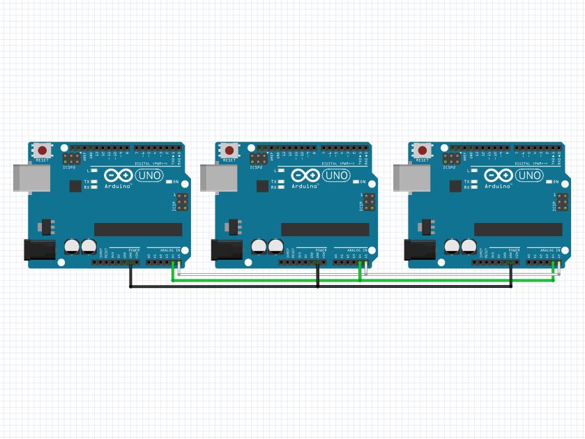
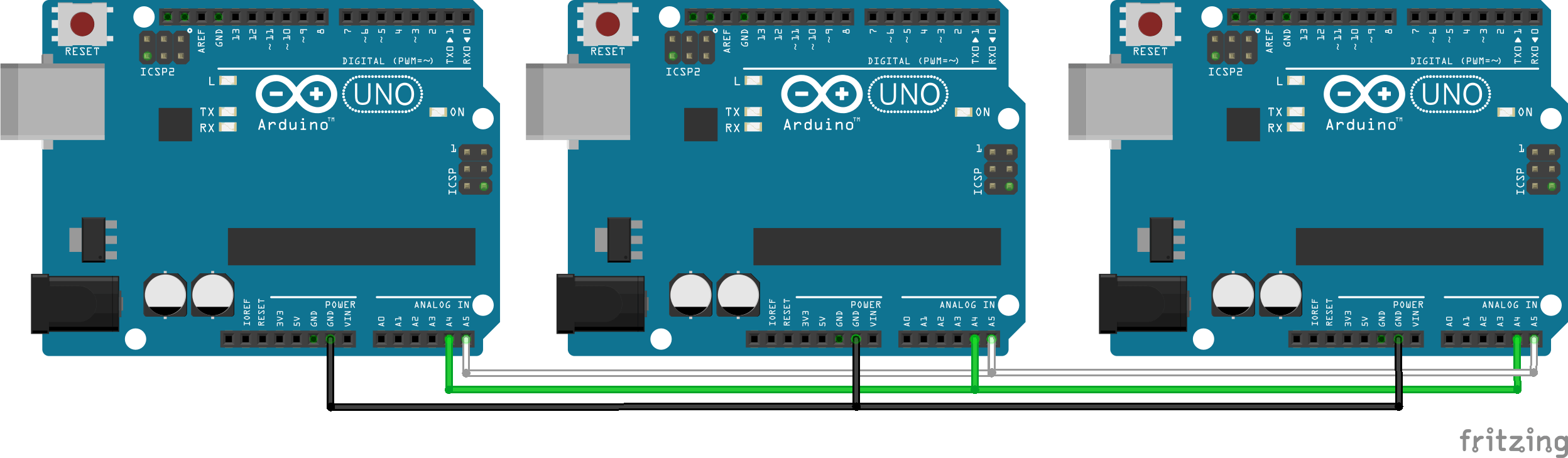
Connection diagram of the I2C bus between Arduino boards
With the I2C protocol, it is also possible to communicate between different systems (sensors, LCD screen, Raspberry Pi, etc.). An interesting example is the communication between several Arduino boards. For that, we have to write at least two programs, one for the “Mistress” card (Master) and the other for the “Slaves” cards.
An I2C communication is defined by a two-wire bus (sometimes called TWI, Two Wire Interface) and an address. The pins used by I2C communication are usually fixed for each device. One on which the data is sent (SDA Serial Data Line) and on the other the synchronization clock (SLC Serial Clock Line).
I2C / TWI pins:
- Uno, Ethernet A4 (SDA), A5 (SCL)
- Mega2560 20 (SDA), 21 (SCL)
- Leonardo 2 (SDA), 3 (SCL)
- Due 20 (SDA), 21 (SCL), SDA1, SCL1
In this example we use an Arduino Uno board, so the pins A4 and A5.
In order for the two cards to communicate with each other, they must be connected correctly (A4 with A4 and A5 with A5) and do not forget to connect the earths (GND) as shown in the following diagram.
Caution: If pins A4 and A5 are connected to the pins of a non-powered card, the code will freeze at the time of transmission.
Generally, one card will send information (Writer) and another will receive it (Reader).
I2C bus configuration code
The Wire.h library allows you to easily define the serial communication on the I2C bus. The functions are similar to the Serial library.
- Wire.begin () initializes the device address. Function argument may be empty for master devices
- Wire.write () allows you to send bytes.
- Wire.requestFrom () handles the request receive function
- Wire.beginTransmission () starts transmitting data and defines the receiver.
- Wire.endTransmission ends data transmission
- Wire.onRequest () handles the request receive function
- Wire.onRecieve () manages the data reception function
Code of the “Master” card
#include <Wire.h>

# define I2C_SLAVE1_ADDRESS 11
# define I2C_SLAVE2_ADDRESS 12

#define PAYLOAD_SIZE 2

int n=0;

void setup()
{
  Wire.begin();
  Serial.begin(9600);

  Serial.println(F("-------------------------------------I am the Master"));
  delay(1000);

  //Request value of n to slave
  Wire.requestFrom(I2C_SLAVE1_ADDRESS, 1);
  n = Wire.read();
  Serial.print(F("recieved value : "));
  Serial.println(n);

  //Send value 12 to slave
  Wire.beginTransmission(I2C_SLAVE1_ADDRESS);
  Wire.write(12);
   Serial.print(F("sending value : "));
  Serial.println(12);
  Wire.endTransmission();

  Serial.print(" ");

  //Request value of n to slave after change
  Wire.requestFrom(I2C_SLAVE1_ADDRESS, 1);
  n = Wire.read();
  Serial.print(F(" new recieved value : "));
  Serial.println(n);
}


void loop()
{
  delay(100);
}
“Slave” card code
#include <Wire.h>

# define I2C_SLAVE_ADDRESS 11 // 12 pour l'esclave 2 et ainsi de suite

#define PAYLOAD_SIZE 2

void setup()
{
  Wire.begin(I2C_SLAVE_ADDRESS);
  Serial.begin(9600);
  Serial.println("-------------------------------------I am Slave1");
  delay(1000);
  Wire.onRequest(requestEvents);
  Wire.onReceive(receiveEvents);
}

void loop(){}

int n = 0;

void requestEvents()
{
  Serial.println(F("---> recieved request"));
  Serial.print(F("sending value : "));
  Serial.println(n);
  Wire.write(n);
}

void receiveEvents(int numBytes)
{
  Serial.println(F("---> recieved events"));
  n = Wire.read();
  Serial.print(numBytes);
  Serial.println(F("bytes recieved"));
  Serial.print(F("recieved value : "));
  Serial.println(n);
}
Open the slave card serial monitor before the master card monitor.
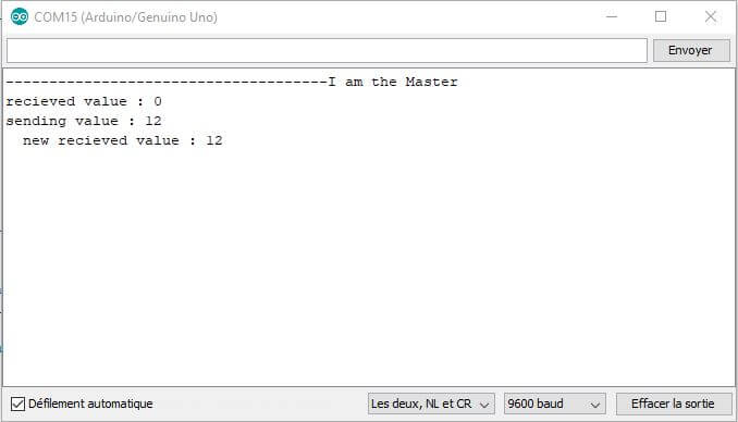
In the serial monitor of the “Master” card:
In the serial monitor of the “Slave 1” card:
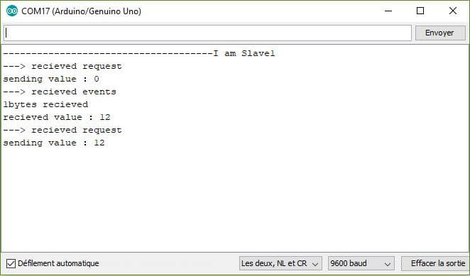
We can see that the two cards are exchanging information. It is very easy to extend this example to several Arduino boards (Leonardo, Mini, etc.) by adapting the wiring and the address of the components in the “Slave” code.
Code to identify the devices connected to the I2C bus
A good test to know if your devices communicate well with each other is to use the code below (I2CScanner) ) which returns all the addresses of the devices connected to the Master card.
    #include <Wire.h>


    void setup()
    {
      Wire.begin();
      Serial.begin(9600);
      while (!Serial);             // Leonardo: wait for serial monitor
      Serial.println(F("\nI2C Scanner"));
    }


    void loop()
    {
      byte error, address;
      int nDevices;

      Serial.println(F("Scanning..."));

      nDevices = 0;
      for(address = 1; address < 127; address++ )
      {
        // The i2c_scanner uses the return value of
        // the Write.endTransmisstion to see if
        // a device did acknowledge to the address.
          Wire.beginTransmission(address);
          error = Wire.endTransmission();


        if (error == 0)
        {
          Serial.print("I2C device found at address 0x");
          if (address<16)
            Serial.print("0");
          Serial.print(address,HEX);
          Serial.println("  !");

          nDevices++;
        }
        else if (error==4)
        {
          Serial.print("Unknown error at address 0x");
          if (address<16)
            Serial.print("0");
          Serial.println(address,HEX);
        }
      }
      if (nDevices == 0)
        Serial.println(F("No I2C devices found\n"));
      else
        Serial.println(F("done\n"));

      delay(5000);           // wait 5 seconds for next scan
    }
If you have difficulty setting up I2C communication between different devices, don’t hesitate to leave us a comment or contact us.
Sources
- The reference onla librairie Wire d’Arduino
- ote on the I2C Master Writer and Master Reader
Find other examples and tutorials in our Automatic code generator
Code Architect


I need to I2c connection Do I need up resistor is for Arduino Uno and Arduino mega I2C communication and also how many USB connection cords are required when for I2C when using only one computer?
You don’t need resistor if the wire is short enough. You need three wire for I2C connection SCL/SDA/GND. You can use one USB cable for the UNO and one for the Mega at the same time as the I2C communication.
I have a robot with multiple sensors and therefore require 2 Arduino microcontrollers. the Arduino uni code the wheel or motion of the robot while Arduino mega have the like of imu, encoder, and multiple ultrasonic sensors. how will I use these two Arduino to communicate with each other
Setting an I2C communication between the two Arduino seems to be the best solution.As the arduino Mega has more computing power you should use the mega as Master and the UNO as slave.
I need to connect multiple Arduinos with each other (up-to 10). Each Arduino has some sensors (consider all sensors works well that uses interrupt and digital pins) connected with it. Now, I want to send all of the Arduinos data (connected using I2C) to a single Arduino. Now the Arduino which receives the data of all other Arduinos connected to it, will send the data to raspberry pi on a single USB (serial) port.
The question is: will the above explained scenario work well using I2C communication as mentioned in this post?
Hi, you can link 10 arduino without issue excpet if your sensors use I2C as well.
You can also linked the arduinos with RaspberryPi using I2C.
The limitations will be:
I2C is meant to be on-board communication so it doesn’t work well for distances over one meter.
You might want to try a I2C buffer to increase the range.
For long distances, consider radio signal, rs232 or rs485 communication.
hi Muhammad;
I am working in a project the same as yours, which needs 8 MCUs with each MCU has sensors. now I am trying to figure out the I2C communication between the one master and the 8 salves, how to give different address for each one of them
Hi,
Usually you select adress in the function setup
Wire.begin(I2C_SLAVE_ADDRESS)
Hi, thanks for sharing great work.
I have 16 x RFID 125KHz readers, all scanning at once.
They communicate over UART.
My question is, if I connect all readers with different Arduinos, and scan Arduinos one by one, using the above configuration, can one Arduino manage to handle the case scenario?
Thanks
Yes of course. You can even plug up to 4 rfid readers to one Arduino.
Hi. I would like to connect 3 Arduinos in i2c configuration where the two Arduino Unos are the slave devices and Arduino Mega is the master device. So is it fine if I copy and paste the I2C scanner code above in the Arduino IDE environment for the Arduino Mega or should I also upload the same code in slave Arduino IDE?
You just need to upload the scanner code in the Arduino Mega but you also need to initialize I2C (Wire.begin) on each slave with different addresses.
But how can I initialize different addresses to the salves when I am trying to find out there addresses?
The Arduino doesn’t have default address or I2C communication activated by default. At some point you will need to upload some code to those arduino in which you initialize I2C and setup an address. In that case the scanner can tell you which arduino is working/connected.
If you were using other module as I2C slave with default address, such as the Motor Shield V2, then the scanner would allow you to display those address.
Hey bro. Can i ask something? I want to send and receive data sensor in int type but i confuse , when i send value more than 255 i get error value , i use thisnfor transmit proximity sensor data from uno to mega.. could you help me!
Can you share the error message? If value cannot be more than 255 you might be trying to send a byte not an int
Hi, I want to send 8 bit operation codes to a network of Arduinos that will in turn trigger the individual Arduinos to perform particular tasks within their own coding. I have envisaged sending them down a common bus but have some of the arduinos ignore the operation codes if they are “not entitled” to recieve them but only activate the Arduinos that are “entitled”. Obviously the entitlement will be coded in the individual arduino. I’m pretty sure from research that this would work, do you have any advice?
This would definitely work. I2C communication seems to be what you’re looking for. You specify the entitled Arduino by sending the operation to his particular and unique I2C address. If the same operation is sent to several Arduinos, you need to send it for each Arduino so the entitlement will be defined in the master. The only drawback is the distance limitation (<1m) but there are some workaround.
Serial (UART) communication could be used adding some coding to define entitlement.
Same could be done using CAN communication.
Hi,
I have a problem with make I2C between UNO and Leonardo. It’s work only with same boards. Leonardo with Leonardo or UNO with UNO.
Where could be the problem?
If you’re using Leonardo, you should put while (!Serial) ; after Serial.begin() in the setup.
Also did you hookup D2 to A4 and D3 to A5?
Are you sure you’re uploading the correct code to the correct board?
Hi!
Someone asked previously about the use of resistors and the answer was “as long as the cable is short enough, resistors are not needed”.
So my question is: If I want to connect multiple Arduinos (ex: 10) via I2C, around 2 meters from each other and one of them as far as 15 meters… do I need resistors? If yes, how do I calculate the value?
Hi,
15meters seems way too long for I2C communication.
You may try pulllup resistor or I2C buffers and reduce communication speed.
But I suggest you switch to Serial communication such as RS485