A photoresistor is an electronic component that measures ambient light. This component is useful in some projects such as a solar panel light follower or home automation to create a smart lamp that only turns on when it is dark or to set up an alarm with a laser diode.
Prerequisite: Give senses to your robot
Material
- Computer
- Arduino UNO
- USB cable to connect Arduino to the computer
- 1x resistor10kOhm
- 1x photoresistor
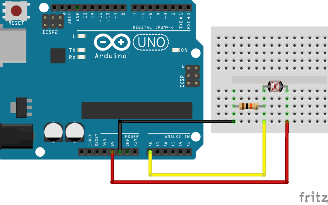
Wiring
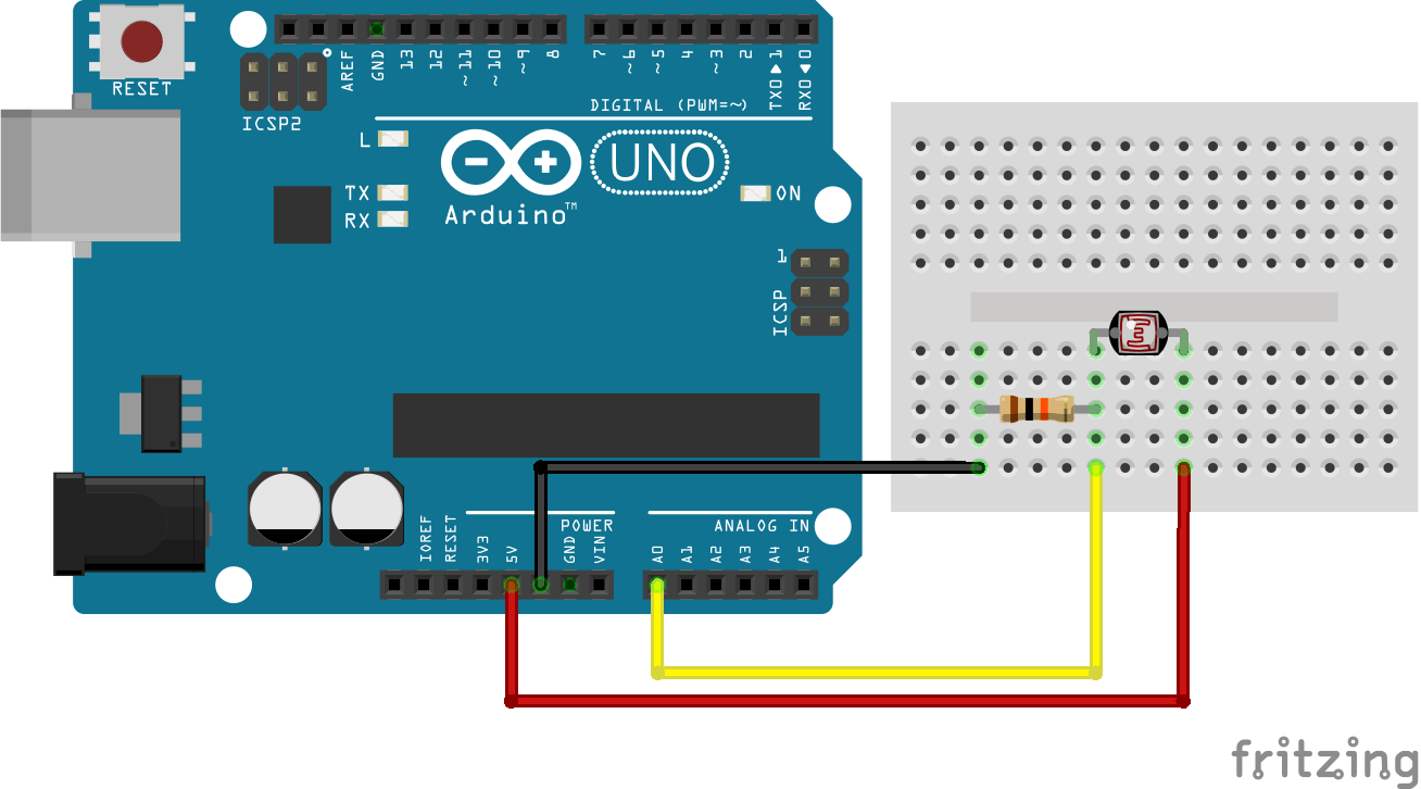
Photoresistor, or Light Dependent Resistor (LDR), is a passive component. To measure a resistance change we have to send a current in the component between two potentials. We therefore create a voltage divider bridge using photoresistor and a resistor of 10kOhm.
Code
To display the physical value of the sensor, we need to know the conversion rule and implement it in a function.
/* Photocell reading program */
// Constants
#define DELAY 500 // Delay between two measurements in ms
#define VIN 5 // V power voltage
#define R 10000 //ohm resistance value

// Parameters
const int sensorPin = A0; // Pin connected to sensor

//Variables
int sensorVal; // Analog value from the sensor
int lux; //Lux value

void setup(void) {
  Serial.begin(9600);
}

void loop(void) {
  sensorVal = analogRead(sensorPin);
  lux=sensorRawToPhys(sensorVal);
  Serial.print("Raw value from sensor= ");
  Serial.println(sensorVal); // the analog reading
  Serial.print("Physical value from sensor = ");
  Serial.print(lux); // the analog reading
  Serial.println(" lumen"); // the analog reading
  delay(DELAY);
}

int sensorRawToPhys(int raw){
  // Conversion rule
  float Vout = float(raw) * (VIN / float(1023));// Conversion analog to voltage
  float RLDR = (R * (VIN - Vout))/Vout; // Conversion voltage to resistance
  int phys=500/(RLDR/1000); // Conversion resitance to lumen
  return phys;
}
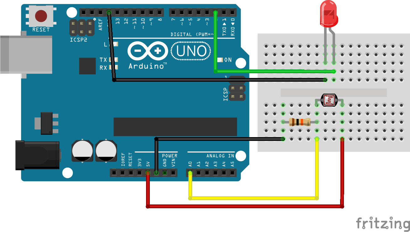
Application
A possible application for a photoresistor is to control a LED lamp depending on luminosity of the room. To do so we simply need to convert the signal of the sensor into a PWM value to command the LED.
/* Photocell controlling lamp program */
// Constants
#define DELAY 200 // Delay between two measurements in ms
#define MIN_RAW 0 // Analog minimum value
#define MAX_RAW 500 // Analog maximum value
#define MIN_CMD 0 // Digital minimum value
#define MAX_CMD 255 // Digital maximum value

// Parameters
const int sensorPin = A0; // Pin connected to sensor
const int ledPin = 3; // Pin connected to sensor

//Variables
int sensorVal; // Analog value from the sensor
int cmd; //Led command value

//Main
void setup(void) {
  Serial.begin(9600);
  pinMode(ledPin,OUTPUT);
}

void loop(void) {
  sensorVal = analogRead(sensorPin);
  cmd=sensorToLed(sensorVal);
  analogWrite(ledPin,cmd);
  delay(DELAY);
  Serial.print("Sensor : ");
  Serial.println(sensorVal);
  Serial.print("Command : ");
  Serial.println(cmd);
}

//Functions
int sensorToLed(int raw){
  // The LED shine when the room is dark
  int val = map(sensorVal, 0, 500, 255, 0);
  val=max(val,MIN_CMD);
  val=min(val,MAX_CMD);
  return val;
}
Source
- http://www.instructables.com/id/How-to-Use-a-Light-Dependent-Resistor-LDR/
- http://www.manuel-esteban.com/arduino-capteur-de-luminosite/
Find other examples and tutorials in our Automatic code generator
Code Architect


