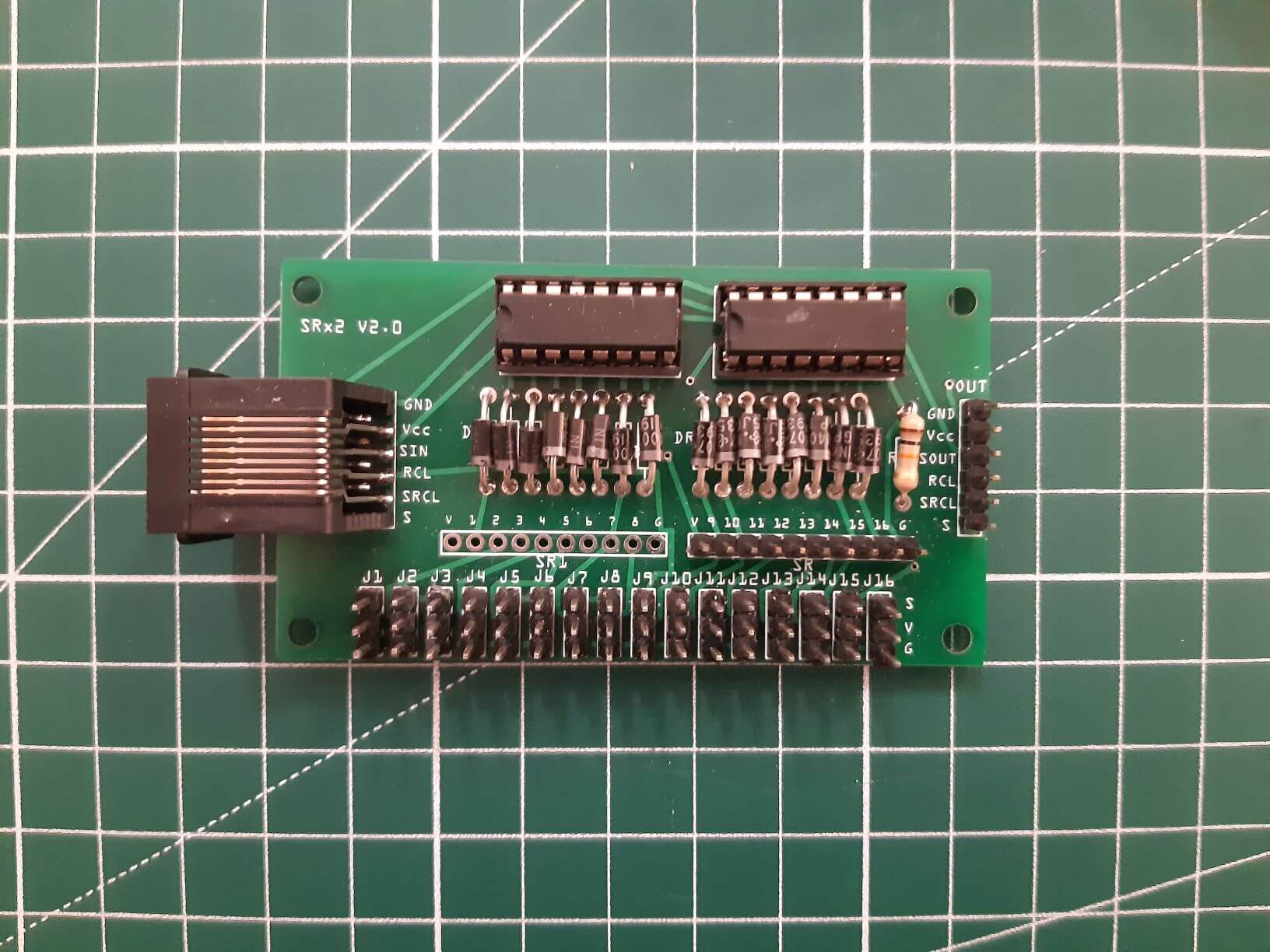
In this project, we’re going to use illuminated buttons and manage buttons and LEDs via the shift register. To do this, we’re going to use a module we’ve developed, the AC SR Breakout Board. This module is an extension board compatible with various microcontrollers, featuring two shift registers and pins for easy component connection.
Hardware
- Arduino microcontroller
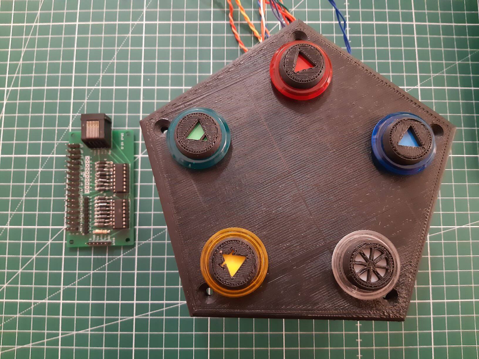
- Illuminated pushbuttons x5 (or buttons + LEDs)
- AC SR Breakout Board shift register module
Principle
The AC SR Breakout Board module consists of two shift registers that we’ll use to manage a group of LEDs and a group of buttons. The outputs of the first shift register will be connected to the buttons, while those of the second will be connected to the LEDs. Several modules can be connected in series to increase the number of inputs and outputs.
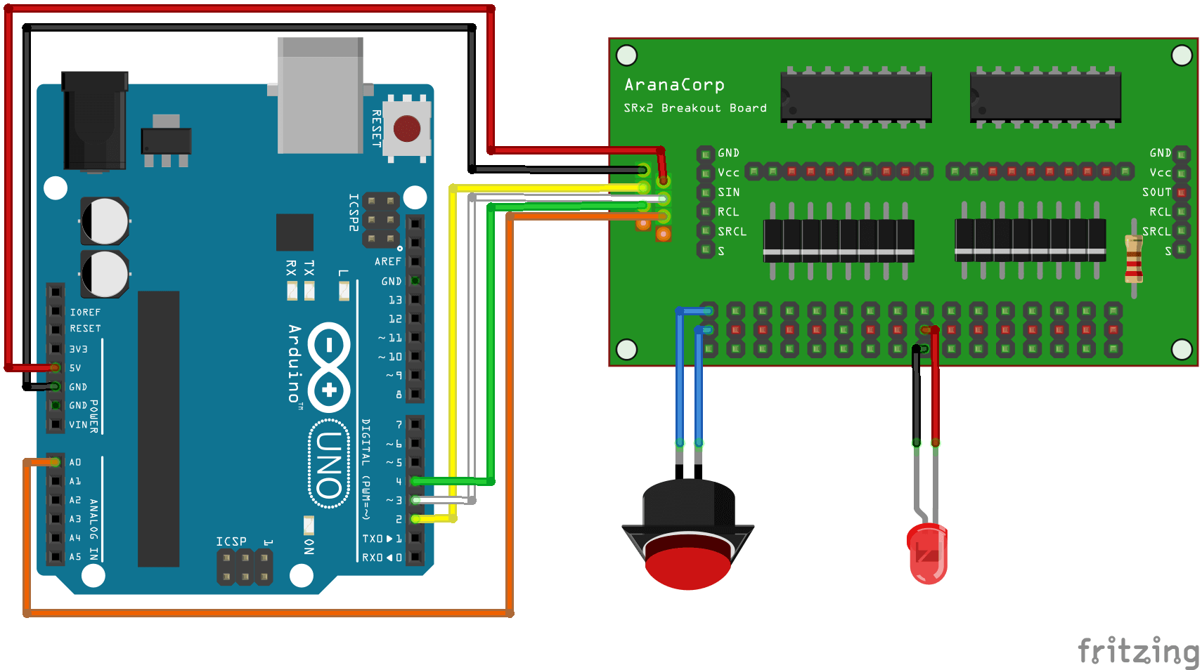
Wiring diagram
N.B.: For clarity’s sake, we’ve only shown one LED and one button on the wiring diagram.
Code
We have already seen how to use shift registers in previous tutorials:
- the basic code for switching LEDs on and off
- Basic code for reading multiple buttons using shift registers
We’ll combine these two codes to light up the LED corresponding to the button pressed. This is particularly useful when working with illuminated buttons. In this project, we’re going to use the luminous buttons as switches to turn their own LEDs on and off.
/ Constants
#define number_of_74hc595s 2
#define numOfRegisterPins number_of_74hc595s * 8
#define SER_Pin 2
#define RCLK_Pin 3
#define SRCLK_Pin 4

//Parameters
const int grpBtnPin = A0;

//Variables
boolean registers[numOfRegisterPins];
boolean grpBtnState[numOfRegisterPins];
boolean grpLedState[numOfRegisterPins];

boolean oldGrpBtnState[numOfRegisterPins];
int grpBtnVal[numOfRegisterPins];

void setup() {
  //Init Serial USB
  Serial.begin(9600);
  Serial.println(F("Initialize System"));
  //Init register
  pinMode(SER_Pin, OUTPUT);
  pinMode(RCLK_Pin, OUTPUT);
  pinMode(SRCLK_Pin, OUTPUT);
  pinMode(grpBtnPin, INPUT_PULLUP);
}

void loop() {
  readGrpBtn();
}

void clearRegisters() { /* function clearRegisters */
  //// Clear registers variables
  for (int i = numOfRegisterPins - 1; i >=  0; i--) {
    registers[i] = LOW;
  }
}

void writeRegisters() { /* function writeRegisters */
  //// Write register after being set
  digitalWrite(RCLK_Pin, LOW);
  for (int i = numOfRegisterPins - 1; i >=  0; i--) {
    digitalWrite(SRCLK_Pin, LOW); int val = registers[i];
    digitalWrite(SER_Pin, val);
    digitalWrite(SRCLK_Pin, HIGH);
  }
  digitalWrite(RCLK_Pin, HIGH);
}

void setRegisterPin(int index, int value) { /* function setRegisterPin */
  ////Set register variable to HIGH or LOW
  registers[index] = value;
}

void readGrpBtn() { /* function readGrpBtn */
  //// Read each btn
  for (int i = numOfRegisterPins - 1; i >=  0; i--) {
    if (i < 16 && i >= 8) {
      grpBtnState[i] = false;
      setRegisterPin(i, HIGH);
      writeRegisters();
      delay(20);
      grpBtnVal[i] = analogRead(grpBtnPin);
      setRegisterPin(i, LOW);
      writeRegisters();
      Serial.println(grpBtnVal[i]);
      if (grpBtnVal[i] > 500) {
        grpBtnState[i] = true;
        if (oldGrpBtnState[i] != grpBtnState[i]) {
          grpLedState[i - 8] = !grpLedState[i - 8];
          Serial.print(F("Btn "));
          Serial.print(i);
          Serial.print(F(" detected -> State =  "));
          Serial.println(grpBtnVal[i]);
        }
      }

    } else { // i<8 && i>=0
      Serial.print("Set LED"); Serial.print(i); Serial.print(" to "); Serial.println(grpLedState[i]);
      setRegisterPin(i, grpLedState[i]);
      writeRegisters();
    }
  }
}
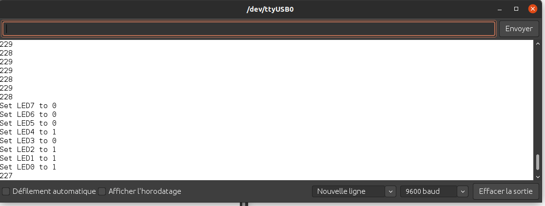
Results
After pressing a few buttons, you can see on the serial monitor that the states of the corresponding LEDs have changed.
Don’t hesitate to leave us a comment to give us your opinion, feedback and suggestions for improvement for this tutorial.
Application
- Building a MIDI console
- Building an interactive HID console


