The radio frequency 433MHz (RF433MHz) is widely used in the field of radio transmissions for remote control or data transmission. It can be found in remote controls or home automation.
Material
- Computer
- Arduino UNO
- USB A Male Cable
- Reed Switch (ILS)
Principle of operation
The 433 MHz RF module is used to transmit information wirelessly on radio waves. The transmitter allows to modulate at high frequency external serial data and to transmit them by radio link to the receiver module. The module is composed of a radio transmitter APF03 and a receiver APRXB12. It uses the ASK modulation (Amplitude Shift Keying) on a frequency of 433 MHz.
RF433MHz radio modules have a range of a few meters (<5m). This range can be greatly increased with a higher voltage source and a properly sized antenna. In theory, up to 100m without obstruction.
Different wireless communication modules exist using different protocols (Wifi, LoRa, etc.) or with higher performance (HC-12, nRF24l01, nRF905, etc.) Check the technical specifications and performance of the module used.
Wiring of RF433MHz modules
In the VirtualWire library that we are going to use, the pins used by default are pin 12 for the “data” pin of the transmitter and pin 11 for the “data” pin of the receiver.
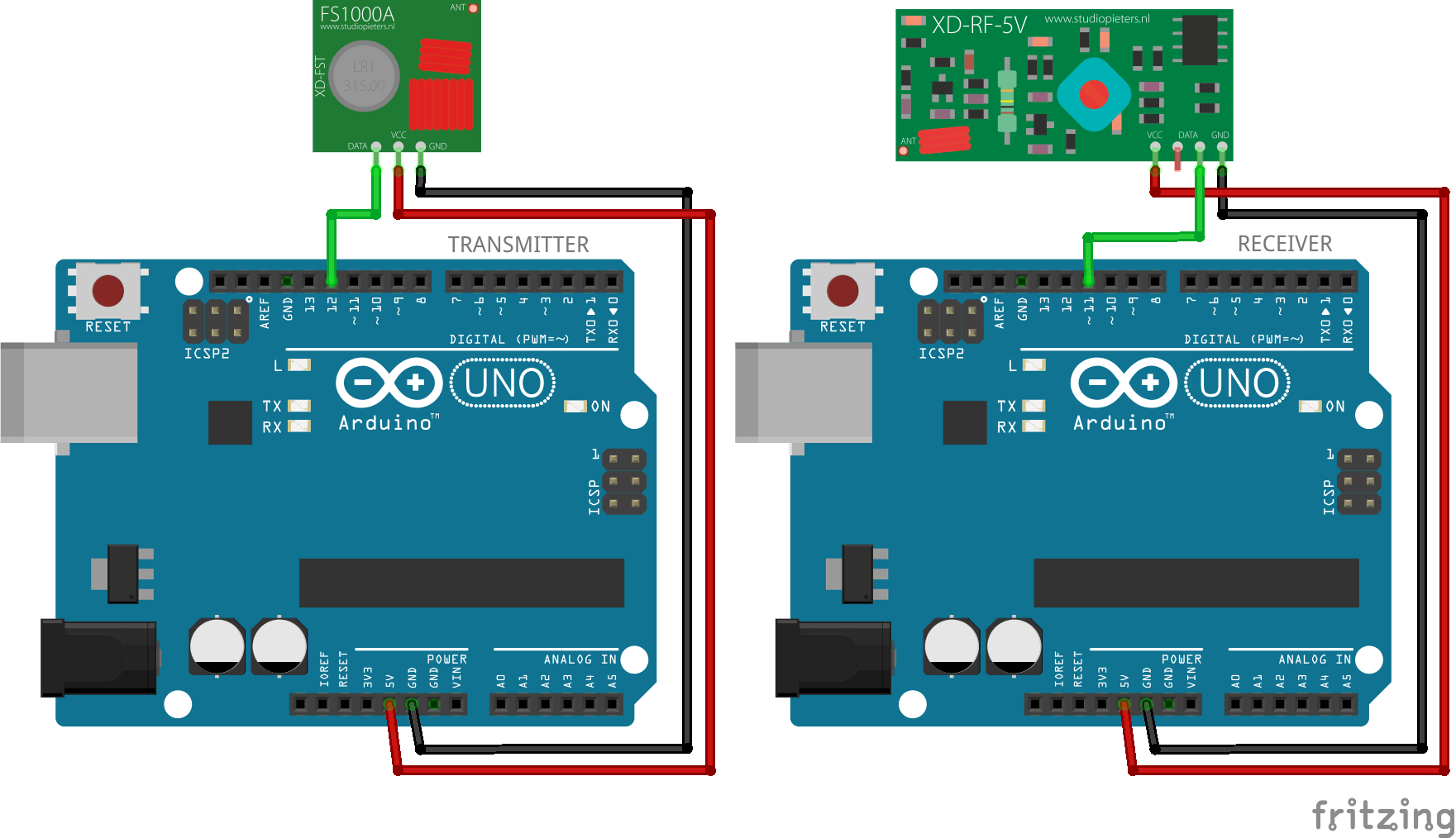
The pin assignment can be different depending on the code and the library used.
Sender code
To start you have to download the VirtualWire library in zip, then in Arduino, go to sketch, include a library, add the .zip library and put the corresponding .zip folder. Once installed, you have to restart Arduino. Once the boards are connected to your PC, choose a different port for each board.
#include <VirtualWire.h>
#define TxPin 12
void setup()
{
  pinMode(13, OUTPUT);
  pinMode(12, INPUT);
  Serial.begin(9600);    // Debugging only
  Serial.println("Setup Transmitter");

  // Initialise the IO and ISR
  vw_set_ptt_inverted(true); // Required for DR3100
  vw_setup(2000);  // Bits per sec
}

void loop()
{
  const char *msg = "Bonsoir tous le monde";

  digitalWrite(13, true); // Flash a light to show transmitting
  vw_send((uint8_t *)msg, strlen(msg));
  vw_wait_tx(); // Wait until the whole message is gone
  digitalWrite(13, false);
  delay(200);
}
Receiver code
#include <VirtualWire.h>
#define RxPin 11
void setup()
{
  pinMode(13, OUTPUT);
  pinMode(11, OUTPUT);
  Serial.begin(9600);  // Debugging only
  Serial.println("Setup Receiver");

  vw_set_ptt_inverted(true); // Required for DR3100
  vw_setup(2000);  // Bits per sec

  vw_rx_start();       // Start the receiver PLL running
}

void loop()
{
  uint8_t buf[VW_MAX_MESSAGE_LEN];
  uint8_t buflen = VW_MAX_MESSAGE_LEN;

  if (vw_get_message(buf, &buflen)) // Non-blocking
  {
    int i;

    digitalWrite(13, true); // Flash a light to show received good message
    // Message with a good checksum received, dump it.
    Serial.print("From transmitter : ");

    for (i = 0; i < buflen; i++)
    {
      //Serial.print(buf[i], HEX);       →sert a afficher les valeurs en héxa
      Serial.print(char(buf[i]));
      //Serial.print(" ");
    }
    Serial.println("");
    digitalWrite(13, false);
  }
}
It is possible to change the pins used with the functions vw_set_rx_pin and vw_set_tx_pin:
//Pour l’émetteur il faut taper
vw_set_tx_pin(txPin);

//Pour le récepteur il faut taper
vw_set_rx_pin(rxPin);
Results
Once the codes have been uploaded to each of the microcontrollers, you should see the message displayed on the receiver’s serial monitor.
Applications
- Remote data transmission
- Remote system control


