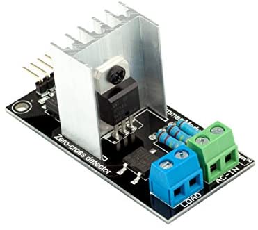
The AC light dimmer is a module that allows to vary the power of an alternating current. It has the same use as a transistor in direct current. It can be used to vary the brightness of a lamp supplied with 220V or to vary the speed of a fan, for example.
Material
- Computer
- Arduino UNO
- USB cable A Male/B Male
- AC Light Dimmer
Principle of operation
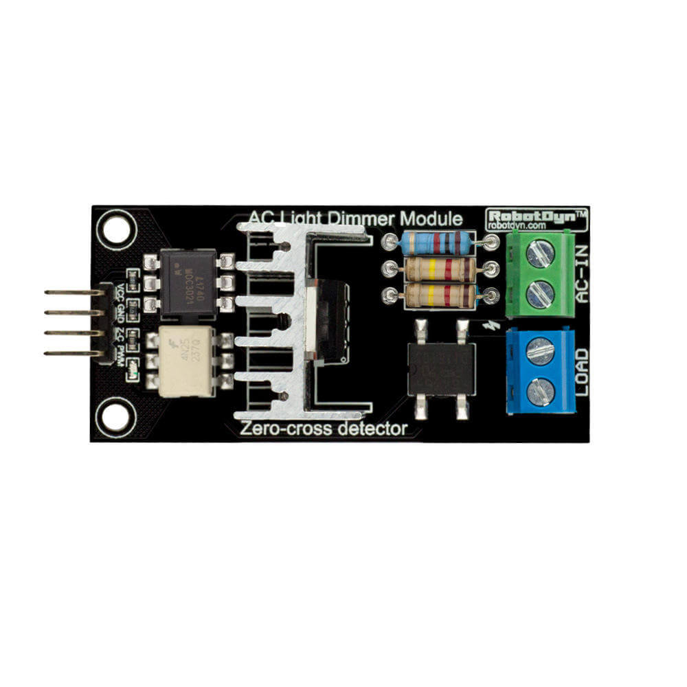
The AC dimmer consists of a triac (equivalent to a DC transistor) and a phase zero crossing detector to synchronize the voltage variation and the phase of the AC current.
Scheme
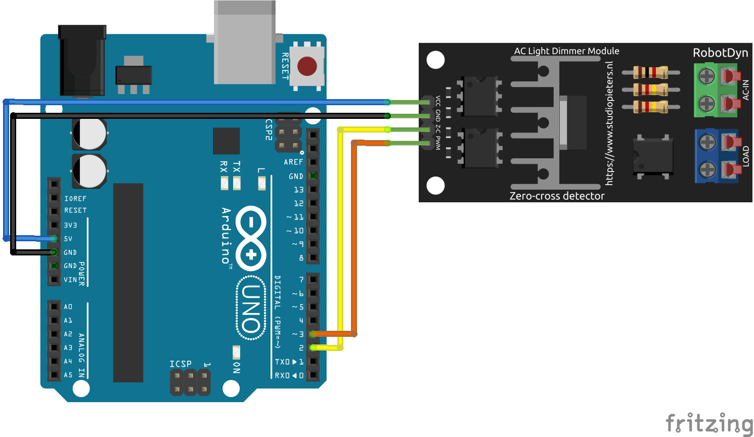
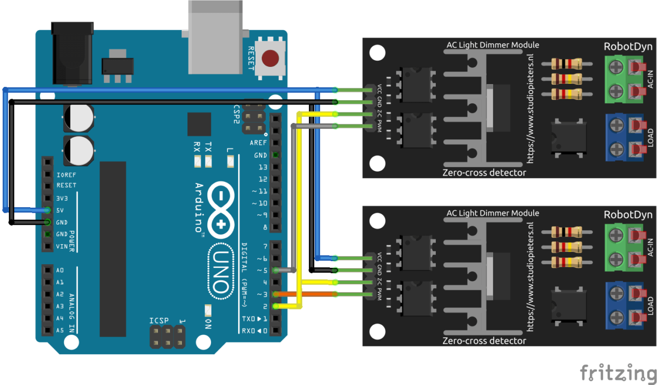
As far as the wiring diagram is concerned, the module is connected to the mains via the AC-IN terminal block and the bulb is connected to the LOAD terminal block. On the electronic side, the pins are connected as follows:
- Vcc at pin 5 or 3.3V of the microcontroller
- GND to ground GND of the microcontroller
- Z-C at pin 2
- PWM on pin 3
If you use several drives, the Z-C pins are all connected to the same microcontroller pin (in our case D2). The RBDdimmer library uses some pins in particular, depending on the microcontroller used. Check the documentation of the library to see which pins you can use.
Code
To use the AC Light Dimmer module, we use the RBDdimmer.h library. The library will manage the synchronization between the PWM signal, which sets the power, and the phase of the AC current. Once the library has been imported and the module initialized, we only have to choose the power level between 0 and 100%.
//Libraries
#include <RBDdimmer.h>//https://github.com/RobotDynOfficial/RBDDimmer
//Parameters
const int zeroCrossPin = 2;
const int acdPin = 3;
int MIN_POWER = 0;
int MAX_POWER = 80;
int POWER_STEP = 2;
//Variables
int power = 0;
//Objects
dimmerLamp acd(acdPin);
void setup(){
//Init Serial USB
Serial.begin(9600);
Serial.println(F("Initialize System"));
acd.begin(NORMAL_MODE, ON);
}
void loop(){
testDimmer();
}
void testDimmer(){/* function testDimmer */
////Sweep light power to test dimmer
for(power=MIN_POWER;power<=MAX_POWER;power+=POWER_STEP){
acd.setPower(power); // setPower(0-100%);
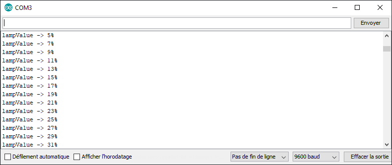
Serial.print("lampValue -> ");
Serial.print(acd.getPower());
Serial.println("%");
delay(100);
}
for(power=MAX_POWER;power>=MIN_POWER;power-=POWER_STEP){
acd.setPower(power); // setPower(0-100%);
Serial.print("lampValue -> ");
Serial.print(acd.getPower());
Serial.println("%");
delay(100);
}
}
Result
The brightness of the bulb varies according to the ‘power’ value sent to the module. It is good to note that this module works with dimmable loads and works best with incandescent bulbs. I use an LED bulb and the dimming works well between 6% and 40%. Below 6%, the lamp goes out, above that, I don’t see any change in brightness and the bulb goes out above 85%.
Bonus: Management of two AC drives
If you want to use another AC drive at the same time, simply connect the Z-C pin to pin 2 (on UNO) and the PWM pin to pin 5 (or another PWM pin).
In the code, to manage two modules, an additional dimmerLamp object must be declared by initializing the correct output pin.
//Libraries
#include <RBDdimmer.h>//https://github.com/RobotDynOfficial/RBDDimmer

//Constants
#define nbACD 2

//Parameters
const int zeroCrossPin = 2;
const int acdPin[nbACD] ={3,5};
int MIN_POWER[nbACD] ={0,0};
int MAX_POWER[nbACD] ={80,80};
int POWER_STEP[nbACD] ={1,1};

//Variables
int power[nbACD] ={0,0};
dimmerLamp acd[nbACD] ={dimmerLamp(acdPin[0]),dimmerLamp(acdPin[1])};

void setup(){
//Init Serial USB
Serial.begin(9600);
Serial.println(F("Initialize System"));
for(int i=0;i<nbACD;i++) acd[i].begin(NORMAL_MODE, ON);
}

void loop(){
  testDimmer();
}

void testDimmer(){/* function testDimmer */
////Sweep light power to test dimmer
for(int i=0;i<nbACD;i++){
  for(power[i]=MIN_POWER[i];power[i]<=MAX_POWER[i];power[i]+=POWER_STEP[i]){
    acd[i].setPower(power[i]); // setPower(0-100%);
      Serial.print(F("lampValue "));Serial.print(i);Serial.print(F(" -> "));
      Serial.print(acd[i].getPower());
      Serial.println(F("%"));
    delay(100);
  }

  for(power[i]=MAX_POWER[i];power[i]>=MIN_POWER[i];power[i]-=POWER_STEP[i]){
    acd[i].setPower(power[i]); // setPower(0-100%);
      Serial.print(F("lampValue "));Serial.print(i);Serial.print(F(" -> "));
      Serial.print(acd[i].getPower());
      Serial.println(F("%"));
    delay(100);
  }
}
}
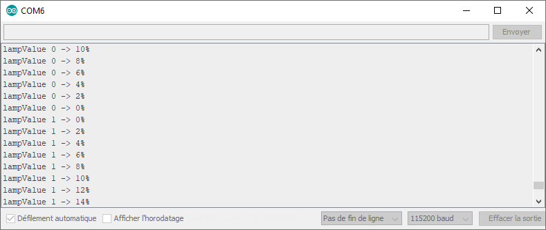
The two lamps turn on and off gradually, one after the other. You can now apply this tutorial to manage all the lamps in your house.
Applications
- Control the brightness of a room according to the time of day
- Control the speed of a fan according to the room temperature
Sources
- https://robotdyn.com/ac-light-dimmer-module-1-channel-3-3v-5v-logic-ac-50-60hz-220v-110v.html
- https://github.com/RobotDynOfficial/RBDDimmer
Retrouvez nos tutoriels et d’autres exemples dans notre générateur automatique de code
La Programmerie


kindly delete my comment. It came to my senses that this is not the board’s manufacturer site!
Will do! thanks for the comment
Thank you very much!
You’re welcome 😉
I don’t think so
Thanks for this, works well and stable.
Tell me, how do you control the brightness?
It turns on and off at most but not even that! No switch, no potentiometer!
Hello, are you using a dimmable bulb light?
acd.setPower(power); // setPower(0-100%);