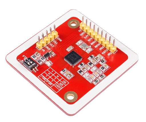
The NFC module PN532 is a smart card reader that, among other things, activates a mechanism when the correct card is presented to the reader. It can be found in smartphones, for example. The RC522 module is certainly the best known RFID module in the Arduino world, but in this tutorial we will see how to use the PN532 RFID reader, which has certain advantages, particularly in terms of communication options. We will see here how to use the module according to the different communication methods UART, SPI, I2C.
Material
- Computer
- Arduino UNO
- USB A Male/B Male cable
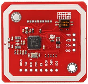
- NFC Module PN532
- Cable Dupont M/F
Selection of the communication mode
One of the big advantages of the NFC module is that it can use different protocols to communicate with Arduino, UART, I2C or SPI. These different protocols use specific pins and libraries of the microcontroller.
To select the communication mode, the PN532 must be configured using the DIP switches (0-Low, 1-High):
| SEL0 | SEL1 | |
| UART | 0 | 0 |
| SPI | 0 | 1 |
| I2C | 1 | 0 |
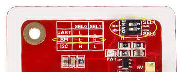
N.B.: Check that the DIP switch settings match the wiring diagrams.
Using the module with Serial communication
Scheme
For serial communication or UART, the pinout is as follows (left side PN532, right side Arduino UNO):
- Vcc (Power supply) <-> 5V
- GND (Ground) <-> GND
- Rx (Data) <-> Tx
- Tx (Clock) <-> Rx
Code
As there are different communication options, the correct library must be used in each case. In the case of a UART port, PN532_HSU.h , for a SoftwareSerial port, PN532_SWHSU.h . The functions allowing NFC reading remain identical in each case.
// for Hardware Serial
/*#include <PN532_HSU.h>
  #include <PN532.h>
  PN532_HSU pn532hsu( Serial );
  PN532 nfc( pn532hsu );
*/

// for Software Serial
#include <SoftwareSerial.h>
#include <PN532_SWHSU.h>
#include <PN532.h>
SoftwareSerial SWSerial( 2, 3 ); // RX, TX
PN532_SWHSU pn532swhsu( SWSerial );
PN532 nfc( pn532swhsu );


String tagId = "None", dispTag = "None";
byte nuidPICC[4];

void setup(void) {

  Serial.begin(115200);
  Serial.println("Hello Maker!");
  //  Serial2.begin(115200, SERIAL_8N1, RXD2, TXD2);

  nfc.begin();

  uint32_t versiondata = nfc.getFirmwareVersion();
  if (! versiondata) {
    Serial.print("Didn't Find PN53x Module");
    while (1); // Halt
  }

  // Got valid data, print it out!
  Serial.print("Found chip PN5"); Serial.println((versiondata >> 24) & 0xFF, HEX);
  Serial.print("Firmware ver. "); Serial.print((versiondata >> 16) & 0xFF, DEC);
  Serial.print('.'); Serial.println((versiondata >> 8) & 0xFF, DEC);

  // Configure board to read RFID tags
  nfc.SAMConfig();

  Serial.println("Waiting for an ISO14443A Card ...");

}

void loop() {
  readNFC();
}

void readNFC() {

  boolean success;
  uint8_t uid[] = { 0, 0, 0, 0, 0, 0, 0 };  // Buffer to store the returned UID
  uint8_t uidLength;                       // Length of the UID (4 or 7 bytes depending on ISO14443A card type)
  success = nfc.readPassiveTargetID(PN532_MIFARE_ISO14443A, &uid[0], &uidLength);

  if (success) {
    Serial.print("UID Length: "); Serial.print(uidLength, DEC); Serial.println(" bytes");
    Serial.print("UID Value: ");

    for (uint8_t i = 0; i < uidLength; i++) {
      nuidPICC[i] = uid[i];
      Serial.print(" "); Serial.print(uid[i], DEC);
    }
    Serial.println();
    tagId = tagToString(nuidPICC);
    dispTag = tagId;
    Serial.print(F("tagId is : "));
    Serial.println(tagId);
    Serial.println("");

    delay(1000);  // 1 second halt

  } else {
    // PN532 probably timed out waiting for a card
    //Serial.println("Timed out! Waiting for a card...");
  }
}

String tagToString(byte id[4]) {
  String tagId = "";
  for (byte i = 0; i < 4; i++) {
    if (i < 3) tagId += String(id[i]) + ".";
    else tagId += String(id[i]);
  }
  return tagId;
}
Using the module with I2C
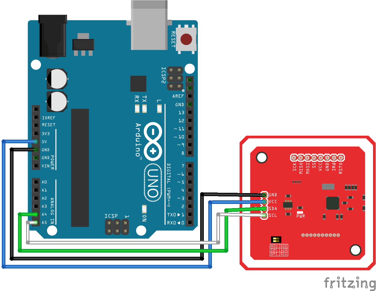
Schéma
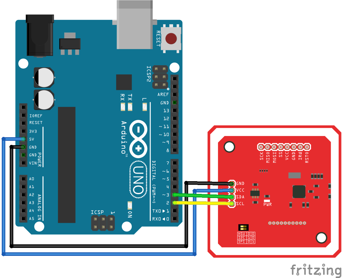
For I2C communication, the pinout is as follows:
- Vcc (Power supply) <-> 5V
- GND (Ground) <-> GND
- SDA (Data) <-> A4
- SCL (Clock) <-> A5
Code for I2C communication
The PN532_I2C.h library for I2C communication
// for I2C Communication
#include <Wire.h>
#include <PN532_I2C.h>
#include <PN532.h>
#include <NfcAdapter.h>
PN532_I2C pn532_i2c(Wire);
NfcAdapter nfc = NfcAdapter(pn532_i2c);

String tagId = "None";
byte nuidPICC[4];

void setup(void) {
  Serial.begin(115200);
  Serial.println("System initialized");

  nfc.begin();
}

void loop() {
  readNFC();
}

void readNFC() {
  if (nfc.tagPresent())
  {
    NfcTag tag = nfc.read();
    tag.print();
    tagId = tag.getUidString();
  }
  delay(5000);
}
Using the module with SPI
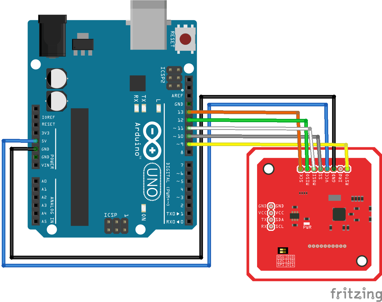
Scheme
For SPI communication, the pinout is as follows:
- Vcc (Power supply) <-> 5V/3V3
- RST (Reset) <-> 9
- GND (Ground) <-> GND
- MISO (Master Input Slave Output) <-> 11
- MOSI (Master Output Slave Input) <-> 12
- SCK (Serial Clock) <-> 13
- SS (Slave select) <-> 10
Code for SPI communication
PN532_SPI.h for communication via the SPI port.
// for SPI Communication
#include <SPI.h>
#include <PN532_SPI.h>
#include <PN532.h>
#include <NfcAdapter.h>
PN532_SPI interface(SPI, 10); // create a PN532 SPI interface with the SPI CS terminal located at digital pin 10
NfcAdapter nfc = NfcAdapter(interface); // create an NFC adapter object


String tagId = "None";

void setup(void) {
  Serial.begin(115200);
  Serial.println("System initialized");

  nfc.begin();
}

void loop() {
  readNFC();
}

void readNFC() {
  if (nfc.tagPresent())
  {
    NfcTag tag = nfc.read();
    tag.print();
    tagId = tag.getUidString();
  }
  delay(5000);
}
Applications
- Lock opening by magnetic card
Sources
- https://github.com/elechouse/PN532
- https://github.com/elechouse/PN532/tree/PN532_HSU/PN532_HSU
- https://github.com/elechouse/PN532/tree/PN532_HSU/PN532_SWHSU
- https://github.com/elechouse/PN532/tree/PN532_HSU/PN532_SPI
- https://github.com/elechouse/PN532/tree/PN532_HSU/PN532_I2C
- https://github.com/elechouse/PN532/tree/PN532_HSU/NDEF
- https://www.arduino.cc/en/reference/wire
- https://www.arduino.cc/en/reference/SPI
Retrouvez nos tutoriels et d’autres exemples dans notre générateur automatique de code
La Programmerie


