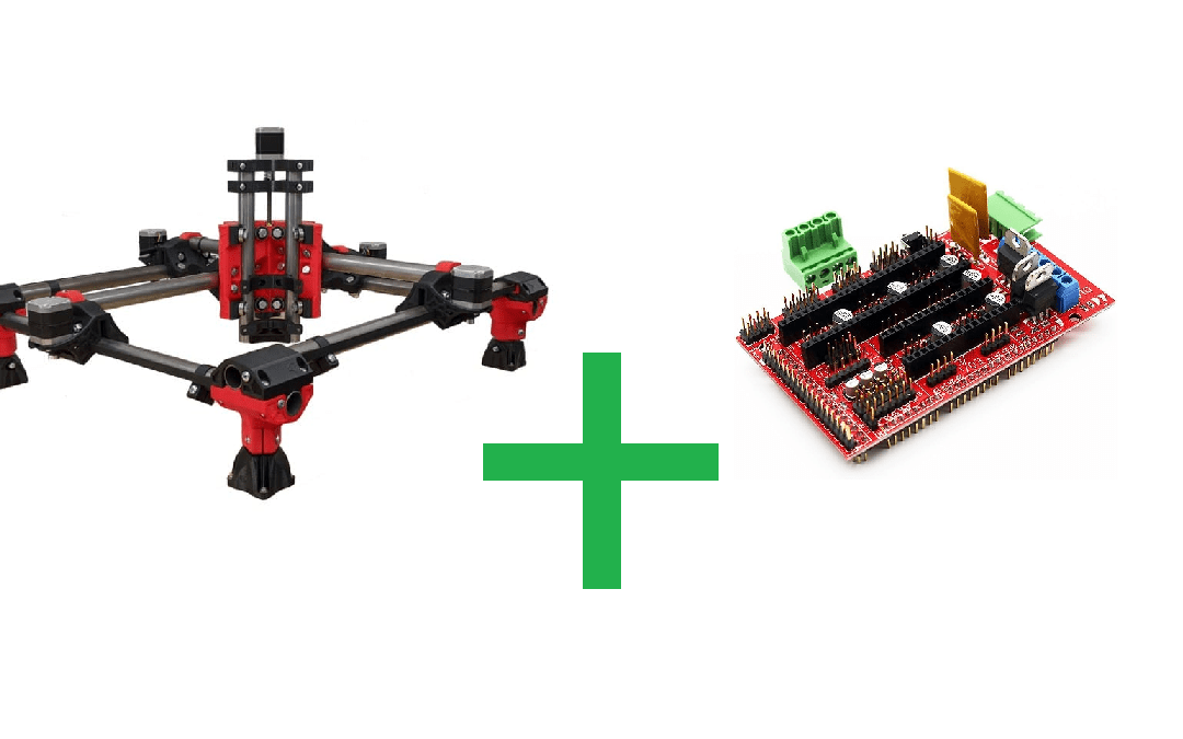
An MPCNC is an acronym for “Mostly Printed CNC”, meaning that it is built primarily from 3D-printed parts. It is a CNC (Computer Numerical Control) machine that can perform machining, engraving, cutting or milling operations on various materials such as wood, plastic or aluminum. The MPCNC is designed to be affordable and easy to build, thanks to its modular architecture and the use of commonly available electronic components. It is based on the principle of a gantry milling machine or Laser, where a mobile carriage moves along 3 axes (X and Y mainly, and Z to adjust tool height slightly) while the tool performs operations on the material. The MPCNC can be controlled by CNC software, which sends precise instructions to the motors to move the axes according to the specified coordinates.Here, we’re relying on V1 Engineering’s MPCNC, to build our very own Graver and Lase Cutter. The Ramps 1.4 board is an electronic extension board used in 3D printers and CNC machines. The term “Ramps” is an acronym for “RepRap Arduino Mega Pololu Shield”. It is specifically designed to work with the Arduino Mega platform and offers a
Hardware
- Ramps 1.4 card
- Arduino Mega 2560
- 5 Stepper motors: 17HS15-1504S-X1
- 3 Stepper motor drivers: DRV8825
- Power supply Output 12V and 20A: S-250-12
- 1 Laser 20W: LD4070HA
- Wires.
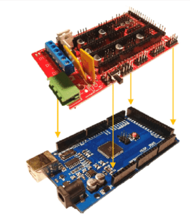
Ramps 1.4 assembly on Arduino Mega
Once you’ve assembled the structure of your MPCNC, you’ll need to assemble the electronics, and for this we’re starting with the Ramps 1.4. As described above, this is a Shield for an Arduino Mega board, which makes assembly fairly straightforward. All you have to do is stack the pins of the 2 boards:
Next, we place the jumpers for the drivers. We need to connect the pins that will be under the drivers on the board such as :
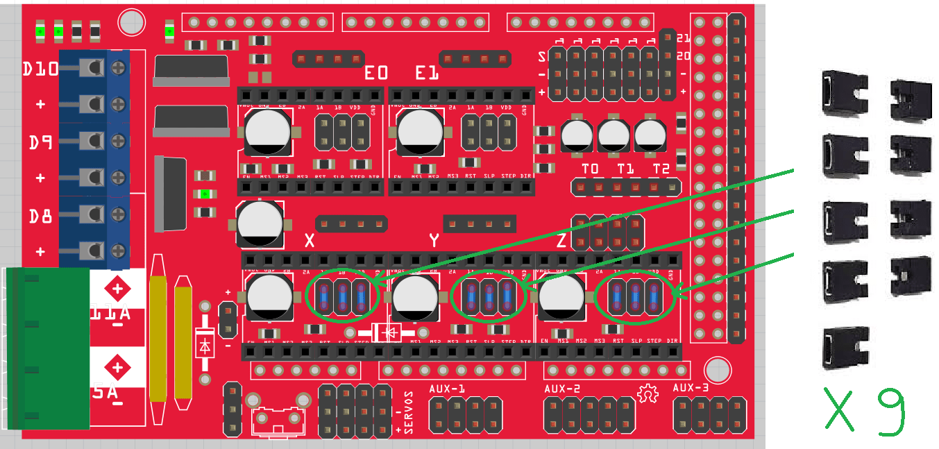
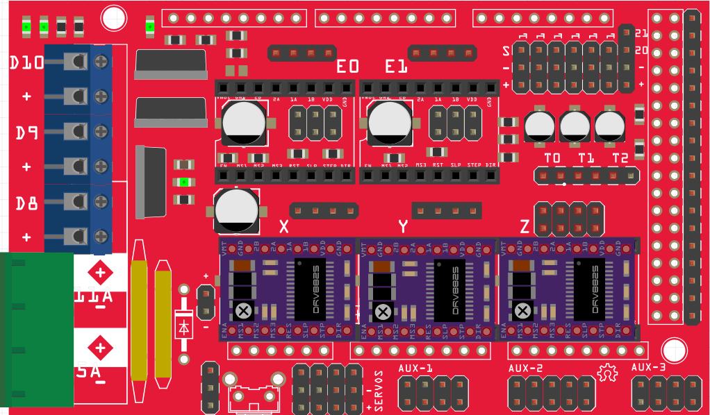
Next, we move on to the stepper motor drivers, which enable communication between the motors and the board. They also have the very important function of limiting the current in the motors to prevent overheating. Simply plug them into the correct pins on the jumpers, such as :
Potentiometer setting for each driver
It is VERY important to do this step correctly, because if the current is too high, it will cause the motors to overheat, which will eventually damage them over long periods. Let’s start by calculating the maximum current to be allowed to flow through the motors. Here, for the DRV8825, we have the following equation: Limit Current = VREF x 2VREF is the voltage measured at the driver terminals and adjusted with the potentiometer and Limit Current is the Current/Phase consumed by your motor, value indicated in the datasheet of your stepper motor. Here, for the 17HS15-1504S-X1 we have Current/Phase = 1.5 ADo to know the value of VREF, we have VREF = Limit Current / 2 = 1.5 / 2 = 0.75 V.However, here, our stepper motors do not carry heavy loads, which require more current. 0.75 V being the maximum, we can reduce this value to limit the overheating of the motors, to 60%. So VREF(decreased) = 0.75 x 0.6 = 0.45 V.
Now, after connecting your board to the 12V power supply (remember to adjust the power supply output voltage with a screwdriver and by measuring the voltage at the output terminals), take a multimeter to measure VREF at the driver terminals as follows:
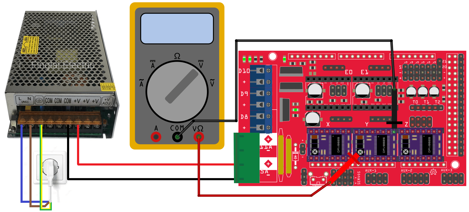
You can measure VREF directly between the driver ground and the potentiometer. To adjust, you’ll need a thin screwdriver to manipulate the potentiometer screw and change the VREF value to the desired voltage, in this case 0.45V.
Stepper motor connection
Once your VREF is set, you can connect the stepper motors. Here, on our machine, we have two stepper motors for each of the X and Y axes, which means you need to connect them in series so they can be controlled by the same driver. They can also be connected in parallel, but we strongly advise against this, as it would consume more current.
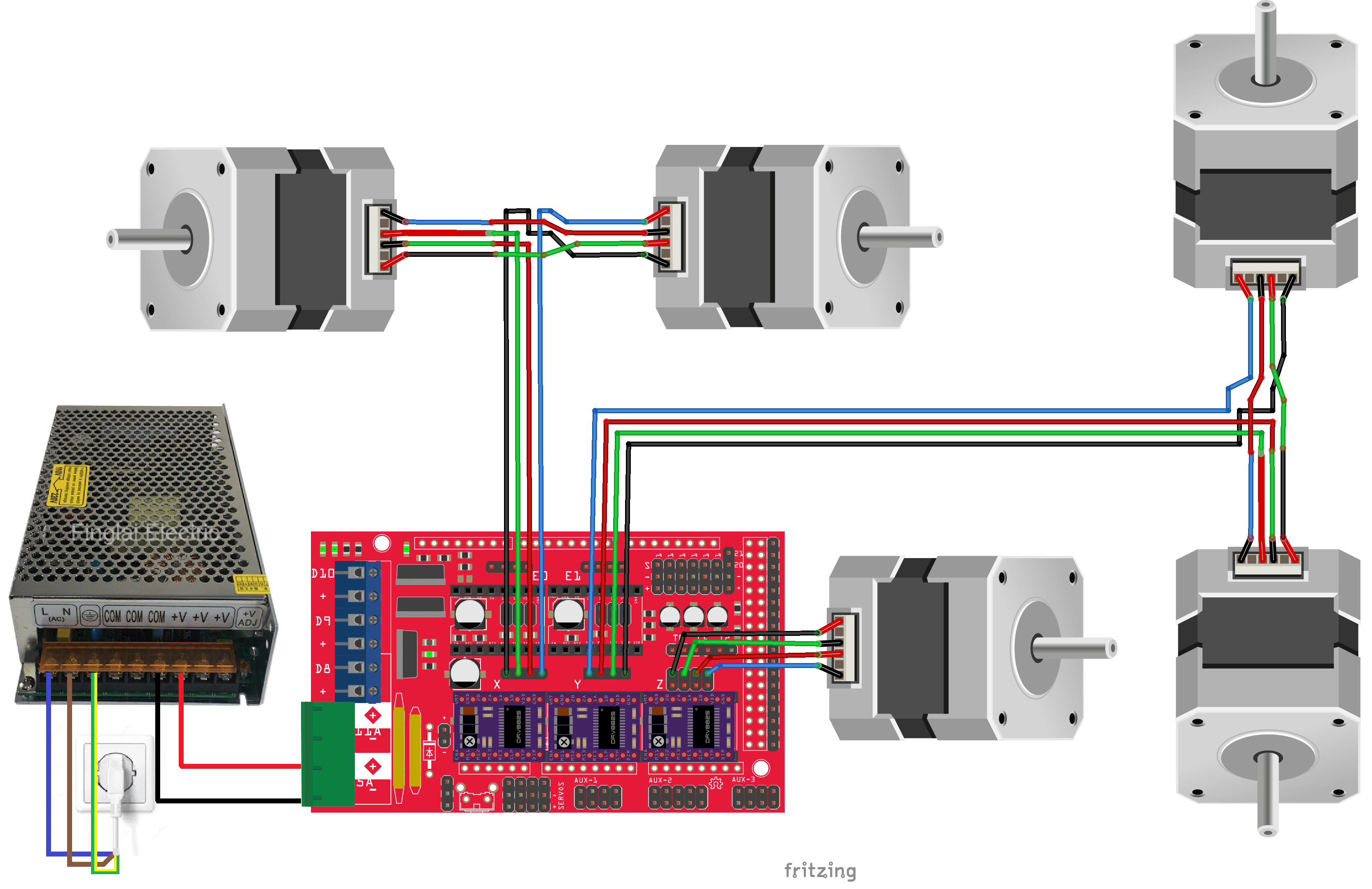
You’ll notice that the stepper motors are connected in series, which means that cables have to be cut and re-soldered. The colors shown on this diagram are those of the cables usually sold with stepper motors. Pay careful attention to the order of the cables when connecting. Also, you’ll notice that the Y axis on the diagram doesn’t have the cable colors in the same order as the others, but in reverse. This is normal; you can reverse the order of the colors connected to the Ramps 1.4 board to reverse the direction of rotation of the motors, so that they match your installation. You’ll need to test them to see if they rotate in the right direction.
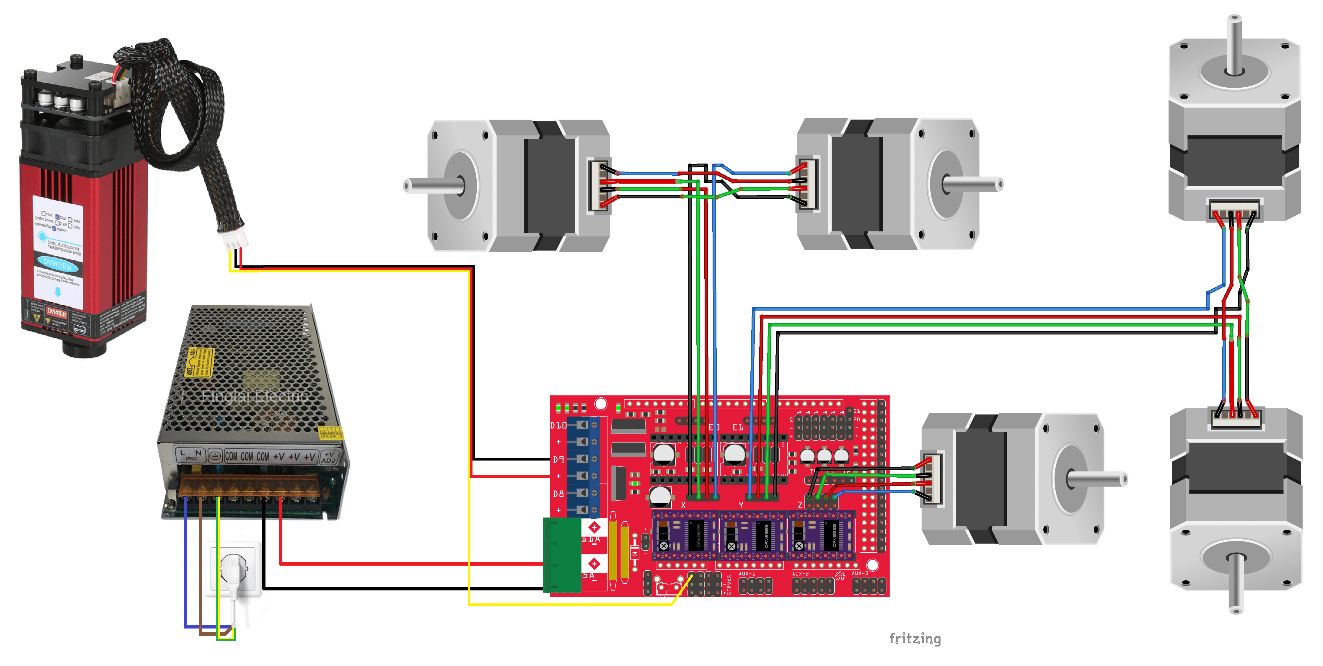
Laser connection
This step may vary, depending on the tool you’re connecting to your MPCNC. Here, we’ll take the LD4070HA 20W laser as an example. We’ll supply it with 12V via pin D9 and control the laser power via pin Digital 11 in PWM.
The electrical wiring is now complete! For software and firmware, follow this tutorial.
Sources :
- https://docs.v1e.com/electronics/ramps/
- https://docs.v1e.com/mpcnc/intro/
- https://docs.v1e.com/electronics/steppers/
- https://forum.v1e.com/t/stepper-motor-voltage/18573
- https://www.youtube.com/watch?v=89BHS9hfSUk
- http://voidmicro.com/Products/Laser/LD4070HA-en.html?page=page_laser


