For this project, we’re going to build a traffic light and reproduce its operation. We’ll take a step-by-step look at how to test each component and develop the final program.
This is a simple project to get you off to a good start learning electronics and programming with Arduino.
Hardware
- Computer
- Arduino UNO
- USB A male to USB B male cable
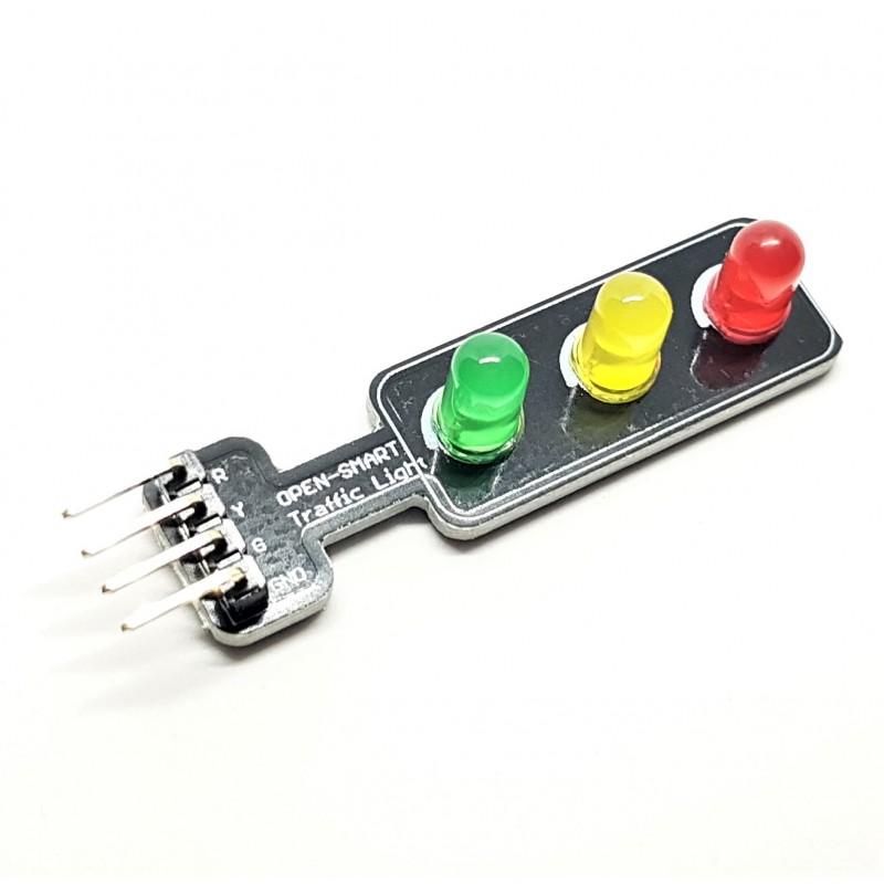
- Traffic light module (or LEDs x3 + resistors x3)
- Pushbutton (or pushbutton module)
- Breadboard
- Dupont M cables
- Push button x1
Objective
We’re going to reproduce the operation of a traffic light. First with an automatic mode in which the LEDs light up one after the other. Then we’ll add a pedestrian call button to force the traffic light to turn red.
Arduino preparation and test code
Without connecting the LEDs, we can already start working on the basic algorithm to test the Arduino’s serial communication and programming. You can follow this tutorial to configure and program the Arduino board.
int verte = 0;
int orange = 1;
int rouge = 2;


void setup() {
  Serial.begin(9600);
  Serial.println("Feux rouge initialisé");
}

void loop() {
  Serial.println("loop running");
  delay(500);
  allumer(verte);
  delay(1000);
  eteindre(verte);
  allumer(orange);
  delay(1000);
  eteindre(orange);
  allumer(rouge);
  delay(1000);
}


void allumer(int color) {
  Serial.print("allumer led ");
  switch (color) {
    case 0:
      Serial.println("verte");
      break;
    case 1:
      Serial.println("orange");
      break;
    case 2:
      Serial.println("rouge");
      break;
  }
}

void eteindre(int color) {
  Serial.print("eteindre led :");
  switch (color) {
    case 0:
      Serial.println("verte");
      break;
    case 1:
      Serial.println("orange");
      break;
    case 2:
      Serial.println("rouge");
      break;
  }
}
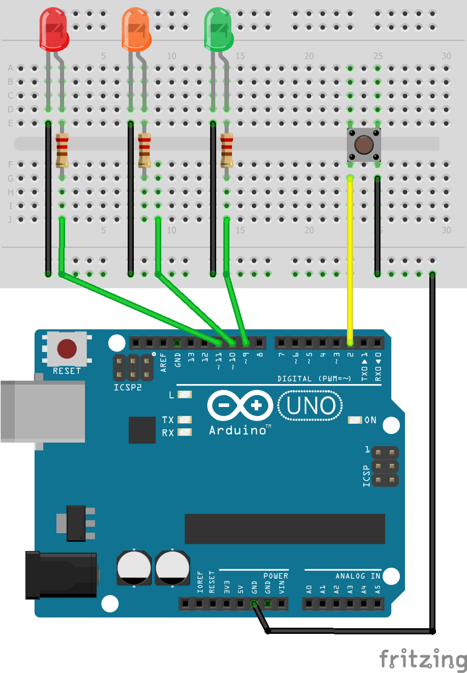
Wiring diagram
The button is connected to pin 2, LED1 to pin 9, LED2 to pin 10 and LED3 to pin 11. Note the presence of resistors to avoid damaging the components. With the traffic light module, these resistors are not necessary.
LED management code
Once the LEDs have been connected to the Arduino, we can try turning them on. The function used to control a diode is digitalWrite(), with the parameter HIGH to turn it on, LOW to turn it off. Simply add the digitalWrite() function to the desired location in the on and off functions.
The aim is to make the green LED light up, then the orange LED, then the red LED after given time intervals.
For greater readability, we’re placing the green, orange and red variables in an enum.
const int pinVerte = 9;
const int pinOrange = 10;
const int pinRouge = 11;

enum couleur {
  VERTE,
  ORANGE,
  ROUGE
};
int etatFeu = VERTE;

void setup() {
  Serial.begin(9600);
  pinMode(pinVerte, OUTPUT);
  pinMode(pinRouge, OUTPUT);
  pinMode(pinOrange, OUTPUT);

  Serial.println("Feu tricolore initialisé");
}

void loop() {
  Serial.println(F("Mode auto running"));
  eteindre (ROUGE);
  allumer (VERTE);
  delay (5000);
  eteindre (VERTE);
  allumer (ORANGE);
  delay (1000);
  eteindre (ORANGE);
  allumer (ROUGE);
  delay (3000);
}


void allumer(int color) {
  Serial.print("allumer led ");
  switch (color) {
    case VERTE:
      Serial.println("verte");
      digitalWrite(pinVerte, HIGH); //analogWrite(pinVerte, 250);
      break;
    case ORANGE:
      Serial.println("orange");
      digitalWrite(pinOrange, HIGH); //analogWrite(pinOrange, 250);
      break;
    case ROUGE:
      Serial.println("rouge");
      digitalWrite(pinRouge, HIGH); //analogWrite(pinRouge, 250);
      break;
    default:
      digitalWrite(pinOrange, HIGH); //analogWrite(pinOrange, 250);
      break;
  }
  etatFeu = color;
}

void eteindre(int color) {
  Serial.print("eteindre led :");
  switch (color) {
    case VERTE:
      Serial.println("verte");
      digitalWrite(pinVerte, LOW); //analogWrite(pinVerte, 0);
      break;
    case ORANGE:
      Serial.println("orange");
      digitalWrite(pinOrange, LOW); //analogWrite(pinOrange, 0);
      break;
    case ROUGE:
      Serial.println("rouge");
      digitalWrite(pinRouge, LOW); //analogWrite(pinRouge, 0);
      break;
    default:
      digitalWrite(pinVerte, LOW); //analogWrite(pinVerte, 0);
      digitalWrite(pinOrange, LOW); //analogWrite(pinOrange, 0); //
      digitalWrite(pinRouge, LOW); //analogWrite(pinRouge, 0); //
      break;
  }
}
LED brightness can be modulated using the analogWrite() function and a PWM output from the microcontroller.
Button management code
We’re now going to test how the push button works. The aim is for the traffic light to change color when the button is pressed. To achieve this, we need to constantly “listen” to the state of the button. An interesting technique for monitoring the state of a sensor is to use an interrupt. Let’s take a look at the code from this complete tutorial on managing a button with an interrupt.
const byte ledPin = 10;
const byte interruptPin = 2;
volatile byte state = LOW;

void setup() {
  Serial.begin(9600);
  pinMode(ledPin, OUTPUT);
  pinMode(interruptPin, INPUT_PULLUP);
  attachInterrupt(digitalPinToInterrupt(interruptPin), onEvent, FALLING);
  Serial.println(F("Système intialisé"));
}

void loop() {
  digitalWrite(ledPin, state);
}

void onEvent() {
  state = !state;
  Serial.print(F("Switch LED : "));
  if (state) {
    Serial.println(F("ON"));
  } else {
    Serial.println(F("OFF"));
  }
}
For other ways to manage the pushbutton, read this tutorial.
Change the light color using the button
We’re going to combine the two previous codes to change the color of the traffic light when the button is pressed.
const int pinVerte = 9;
const int pinOrange = 10;
const int pinRouge = 11;

enum couleur {
  VERTE,
  ORANGE,
  ROUGE
};
int etatFeu = VERTE;

const byte btnPin = 2;
int state = 0;

void setup() {
  Serial.begin(9600);
  pinMode(pinVerte, OUTPUT);
  pinMode(pinRouge, OUTPUT);
  pinMode(pinOrange, OUTPUT);

  pinMode(btnPin, INPUT);
  attachInterrupt(digitalPinToInterrupt(btnPin), onEvent, FALLING);
  Serial.println("Feu tricolore initialisé");
}

void loop() {
  switch (state) {
    case 0://mode automatique
      Serial.println(F("Mode auto"));
      eteindre (ROUGE);
      allumer (VERTE);
      delay (5000);
      eteindre (VERTE);
      allumer (ORANGE);
      delay (1000);
      eteindre (ORANGE);
      allumer (ROUGE);
      delay (3000);
      break;

    case 1:// mode manuel
      Serial.println(("Mode manuel"));
      delay (5000);
      eteindre (ROUGE);

      state = 0;
      break;
  }
}

void onEvent() {
  Serial.println("---> Bouton pressé");
  eteindre(3);//eteindre tout
  allumer (ROUGE);
  state=1;
}


void allumer(int color) {
  Serial.print("allumer led ");
  switch (color) {
    case VERTE:
      Serial.println("verte");
      digitalWrite(pinVerte, HIGH); //analogWrite(pinVerte, 250);
      break;
    case ORANGE:
      Serial.println("orange");
      digitalWrite(pinOrange, HIGH); //analogWrite(pinOrange, 250);
      break;
    case ROUGE:
      Serial.println("rouge");
      digitalWrite(pinRouge, HIGH); //analogWrite(pinRouge, 250);
      break;
    default:
      digitalWrite(pinOrange, HIGH); //analogWrite(pinOrange, 250);
      break;
  }
}

void eteindre(int color) {
  Serial.print("eteindre led : ");
  switch (color) {
    case VERTE:
      Serial.println("verte");
      digitalWrite(pinVerte, LOW); //analogWrite(pinVerte, 0);
      break;
    case ORANGE:
      Serial.println("orange");
      digitalWrite(pinOrange, LOW); //analogWrite(pinOrange, 0);
      break;
    case ROUGE:
      Serial.println("rouge");
      digitalWrite(pinRouge, LOW); //analogWrite(pinRouge, 0);
      break;
    default:
      Serial.println(" tout");
      digitalWrite(pinVerte, LOW); //analogWrite(pinVerte, 0);
      digitalWrite(pinOrange, LOW); //analogWrite(pinOrange, 0); //
      digitalWrite(pinRouge, LOW); //analogWrite(pinRouge, 0); //
      break;
  }
}
If you test this code, you’ll find that the light doesn’t behave quite as expected. We manage to force the color to red, but automatic operation doesn’t resume correctly. This is due to the delay() function blocking the code. To be able to take the button into account when we press it, we’ll have to modify the code to get rid of the delay() function.
Code modification
To remove the delay() function, we can use an algorithm with the millis() function. We will reproduce the delay function using the millis function without blocking the code flow.
  if((millis()-previousTime)>200){
    previousTime=currentTime;
    Serial.println(F("action"));
  }
To do this, we also need to break down the operation of the red light into different states and integrate them into the switch cases. One state for the color change and one state for the delay.
  switch (state) {
    case 0:
      eteindre (ROUGE);
      allumer (VERTE);
      state++;
      previousMillis = millis();
      break;
    case 1:
      if (millis() - previousMillis > 5000) { //delay (5000);
        state++;
      }
      break;
    case 2:
      eteindre (VERTE);
      allumer (ORANGE);
      state++;
      previousMillis = millis();
      break;
    case 3:
      if (millis() - previousMillis > 1000) { //delay (1000);
        state++;
      }
      break;
    case 4:
      eteindre (ORANGE);
      allumer (ROUGE);
      state++;
      previousMillis = millis();
      break;
    case 5:
      if (millis() - previousMillis > 3000) { //delay (3000);
        state = 0;
      }
      break;
  }
Complete final code
Once these changes have been made, the button press is taken directly into account and the traffic light can resume its normal course.
const int pinVerte = 9;
const int pinOrange = 10;
const int pinRouge = 11;

enum couleur {
  VERTE,
  ORANGE,
  ROUGE
};
int etatFeu = VERTE;
int state = 0;

const byte btnPin = 2;
int mode = 0;

unsigned long previousMillis = 0;

void setup() {
  Serial.begin(9600);
  pinMode(pinVerte, OUTPUT);
  pinMode(pinRouge, OUTPUT);
  pinMode(pinOrange, OUTPUT);

  pinMode(btnPin, INPUT);
  attachInterrupt(digitalPinToInterrupt(btnPin), onEvent, RISING);
  Serial.println("Feu tricolore initialisé");
}

void loop() {
  switch (state) {
    case 0:
      eteindre (ROUGE);
      allumer (VERTE);
      state++;
      previousMillis = millis();
      break;
    case 1:
      if (millis() - previousMillis > 5000) { //delay (5000);
        state++;
      }
      break;
    case 2:
      eteindre (VERTE);
      allumer (ORANGE);
      state++;
      previousMillis = millis();
      break;
    case 3:
      if (millis() - previousMillis > 1000) { //delay (1000);
        state++;
      }
      break;
    case 4:
      eteindre (ORANGE);
      allumer (ROUGE);
      state++;
      previousMillis = millis();
      break;
    case 5:
      if (millis() - previousMillis > 3000) { //delay (3000);
        state = 0;
      }
      break;
  }
}

void onEvent() {
  Serial.println("---> Bouton pressé");
  if (etatFeu == VERTE) {
    Serial.println("Changement d'etat");
    state = 2;
  }
}


void allumer(int color) {
  Serial.print("allumer led ");
  switch (color) {
    case VERTE:
      Serial.println("verte");
      digitalWrite(pinVerte, HIGH); //analogWrite(pinVerte, 250);
      break;
    case ORANGE:
      Serial.println("orange");
      digitalWrite(pinOrange, HIGH); //analogWrite(pinOrange, 250);
      break;
    case ROUGE:
      Serial.println("rouge");
      digitalWrite(pinRouge, HIGH); //analogWrite(pinRouge, 250);
      break;
    default:
      digitalWrite(pinOrange, HIGH); //analogWrite(pinOrange, 250);
      break;
  }
  etatFeu = color;
}

void eteindre(int color) {
  Serial.print("eteindre led :");
  switch (color) {
    case VERTE:
      Serial.println("verte");
      digitalWrite(pinVerte, LOW); //analogWrite(pinVerte, 0);
      break;
    case ORANGE:
      Serial.println("orange");
      digitalWrite(pinOrange, LOW); //analogWrite(pinOrange, 0);
      break;
    case ROUGE:
      Serial.println("rouge");
      digitalWrite(pinRouge, LOW); //analogWrite(pinRouge, 0);
      break;
    default:
      digitalWrite(pinVerte, LOW); //analogWrite(pinVerte, 0);
      digitalWrite(pinOrange, LOW); //analogWrite(pinOrange, 0); //
      digitalWrite(pinRouge, LOW); //analogWrite(pinRouge, 0); //
      break;
  }
}
Feel free to leave a comment to share your achievements or give us your feedback. You can also contact us if you have any questions.
Application
- Reproduce a road crossing with 4 synchronized traffic lights


