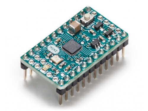
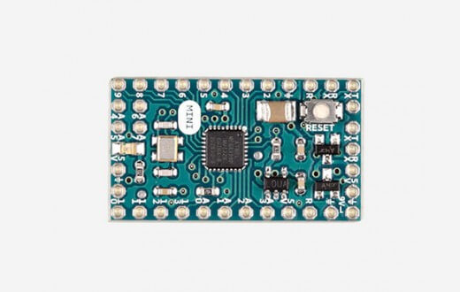
The Arduino MINI board has been designed for projects where space is critical and the configuration is fixed.
Microcontroller features
The Arduino MINI microcontroller uses the ATmega328P microprocessor. This processor operates at a clock frequency of 8(3.3V ver) 16(5V ver) MHz, with 2 kB RAM, 1 kB EEPROM and 32 kB Flash memory (for programming and data storage).
|  |
Power supply
The Arduino MINI microcontroller operates over a voltage range of 3.35-12V (3.3V ver) or 5-12V(5V ver), thanks to its on-board voltage regulator. The microprocessor operates at 3.3 or 5V. In normal operation, the microcontroller consumes up to 45mA (if no power is supplied) and can accept a maximum current of 40mA on each of its IO pins.
Pinout
- Analog I/O : 6 (A0, A1, A2, A3, A4, A5)
- Digital I/O : 8 (0, 1, 2, 4, 7, 8, 12, 13)
- PWM pins: 6 (3, 5, 6, 9, 10, 11)
- Communication Serial: 14 (0, 1, 2, 3, 4, 5, 6, 7, 8, 9, 10, 11, 12, 13)
- I2C communication : 1 ((‘A4’, ‘A5’))
- SPI communication: 1 ((10, 13, 12, 11))
- Interrupt : 1 (2)
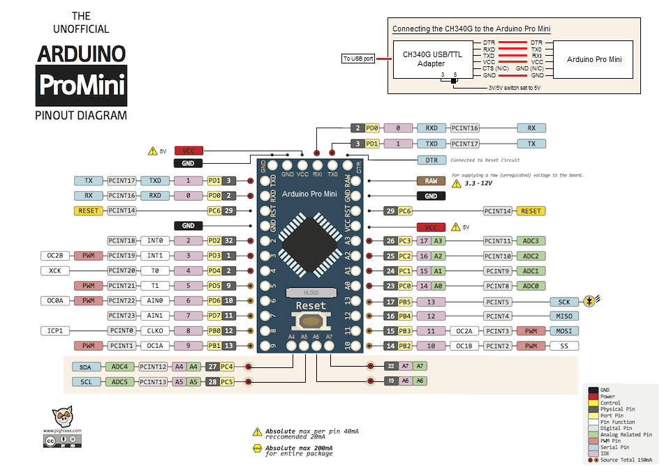
Basic code and pin identification
To use the input/output pins in the code, simply use the labels present on the board, i.e. A0-A5 and 0-13. Pins A0, A1, A2, A3, A4 and A5 can also be replaced by 14, 15, 16, 17, 18 and 19 respectively. For your information, analog pins can also be used as digital I/Os.
const int analogPin=A0; // broches A0-A5 ou 14-19
const int digitalInPin=2; // broches 0-13 et 14-19
const int digitalOutPin=4; // broches 0-13 et 14-19
const int pwmPin=3; // broches 3 5 6 9 10 11

int analogVal=0;
int digitalState=LOW; //LOW or false or 0
int pwmVal=250;

void setup() {
  Serial.begin(9600); //broches 0(Rx) et 1(Tx)

  pinMode(analogPin,INPUT_PULLUP); // broches 0-13 et 14-19, Argument OUTPUT, INPUT, INPUT_PULLUP
  pinMode(digitalInPin,INPUT);
  pinMode(digitalOutPin,OUTPUT);
  pinMode(pwmPin,OUTPUT);
}

void loop() {
 analogVal=analogRead(analogPin); // broches A0-A5 ou 14-19, return int
 digitalState=digitalRead(digitalInPin); // broches 0-13 et 14-19, return boolean
 digitalWrite(digitalOutPin,HIGH); //broches 0-13 et 14-19, valeur LOW(0) ou HIGH(1)
 analogWrite(pwmPin,pwmVal);// broches 3 5 6 9 10 11, valeur 0-255
}
Summary of features
| Microcontrôleur | |
| Nom: | ArduinoMINI |
| Marque: | Arduino |
| Caractéristiques | |
| CPU: | ATmega328P |
| Tension d’alimentation : | 3.35-12V (3.3V ver) or 5-12V(5V ver) |
| Tension logic: | 3.3V ou 5V |
| E/S digitales: | 14 |
| Entrées analogiques: | 6 |
| Flash: | 32kB |
| SRAM: | 2kB |
| EEPROM: | 1kB |
| Fréquence d’horloge: | 8(3.3V ver) 16(5V ver) MHz |
| Wifi: | No |
| Bluetooth: | No |
| SD card: | No |
| Touch: | No |
| UART/SPI/I2C/I2S: | Yes/Yes/Yes/No |


