The multiplexer is an integrated circuit made up of logic circuits allowing several signals to be concentrated on the same output (mutiplexing or mux) or to connect an input to one of its N outputs (demultiplexing or demux). In this tutorial, we will see the use of the CD4051 integrated circuit which can be used as a multiplexer and demultiplexer from one to eight channels. It can be used to drive LEDs or to retrieve the state of several sensors.
Hardware
- Computer
- Arduino UNO
- USB cable A Male to B Male
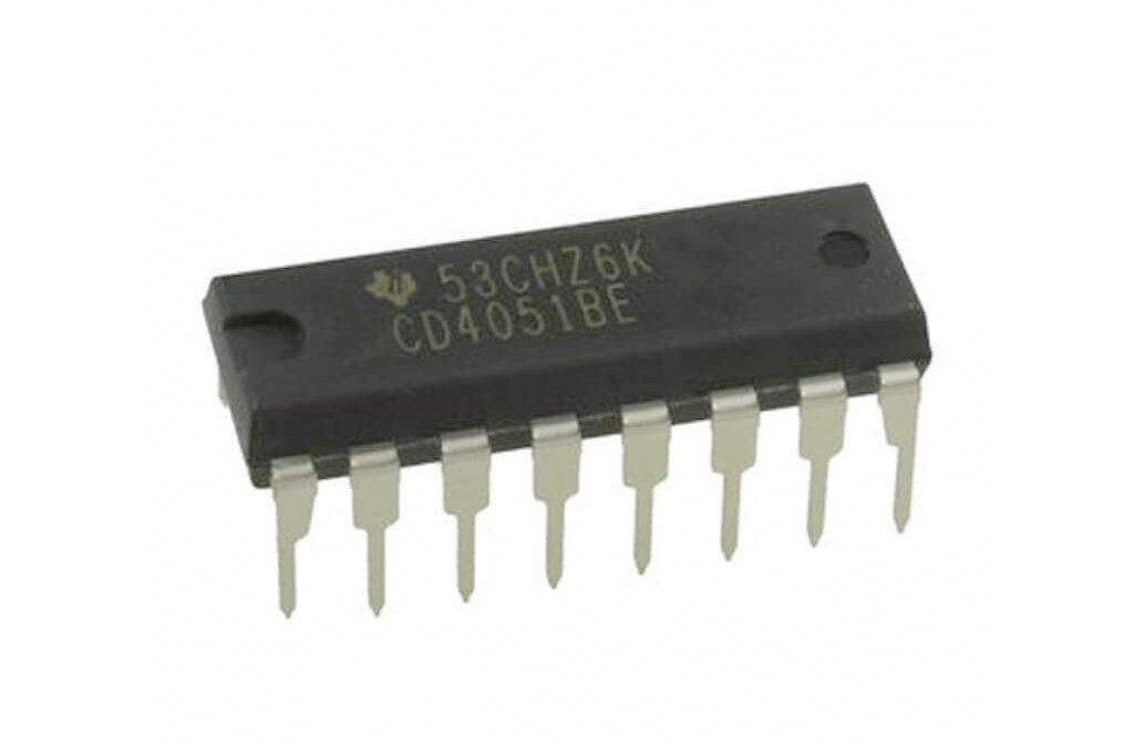
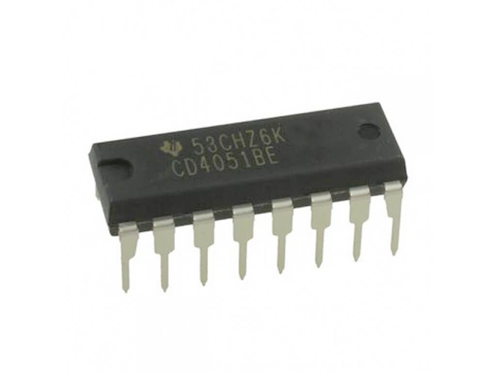
- Multiplexer
Principle of operation
The multiplexer/demultiplexer is an electronic component containing a logic circuit allowing selection from 8 channels. If the miltiplexer is activated, the common (IN/OUT) is connected directly to the selected channel.
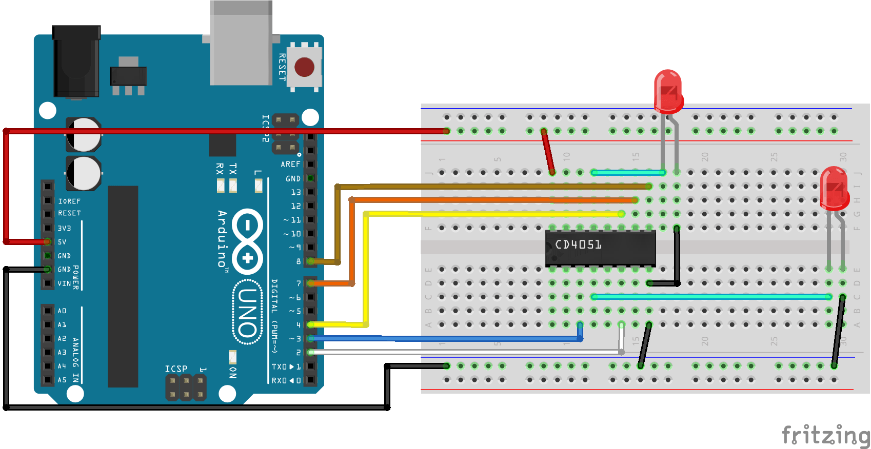
Schematics
The multiplexer requires 3 output pins from a microcontroller. Plus one channel to activate or deactivate the integrated circuit. It is possible to connect this signal to ground if the multiplexer is always connected to one channel.
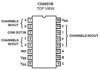
- VSS integrated circuit ground
- Vcc power supply pin. Usually connected to 5V
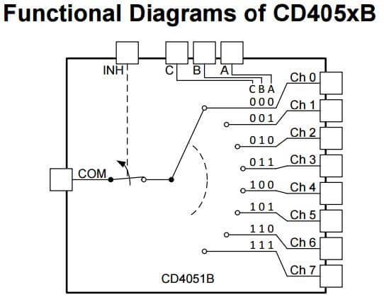
- A,B,C Channel selection signals
- CH0-CH7 multiplexing channels
- COM Common input/output. Common input/output. Pin to which the multiplexed signal or the signal to be demultiplexed arrives.
- INH Inhibit, active LOW. Integrated circuit activation pin.
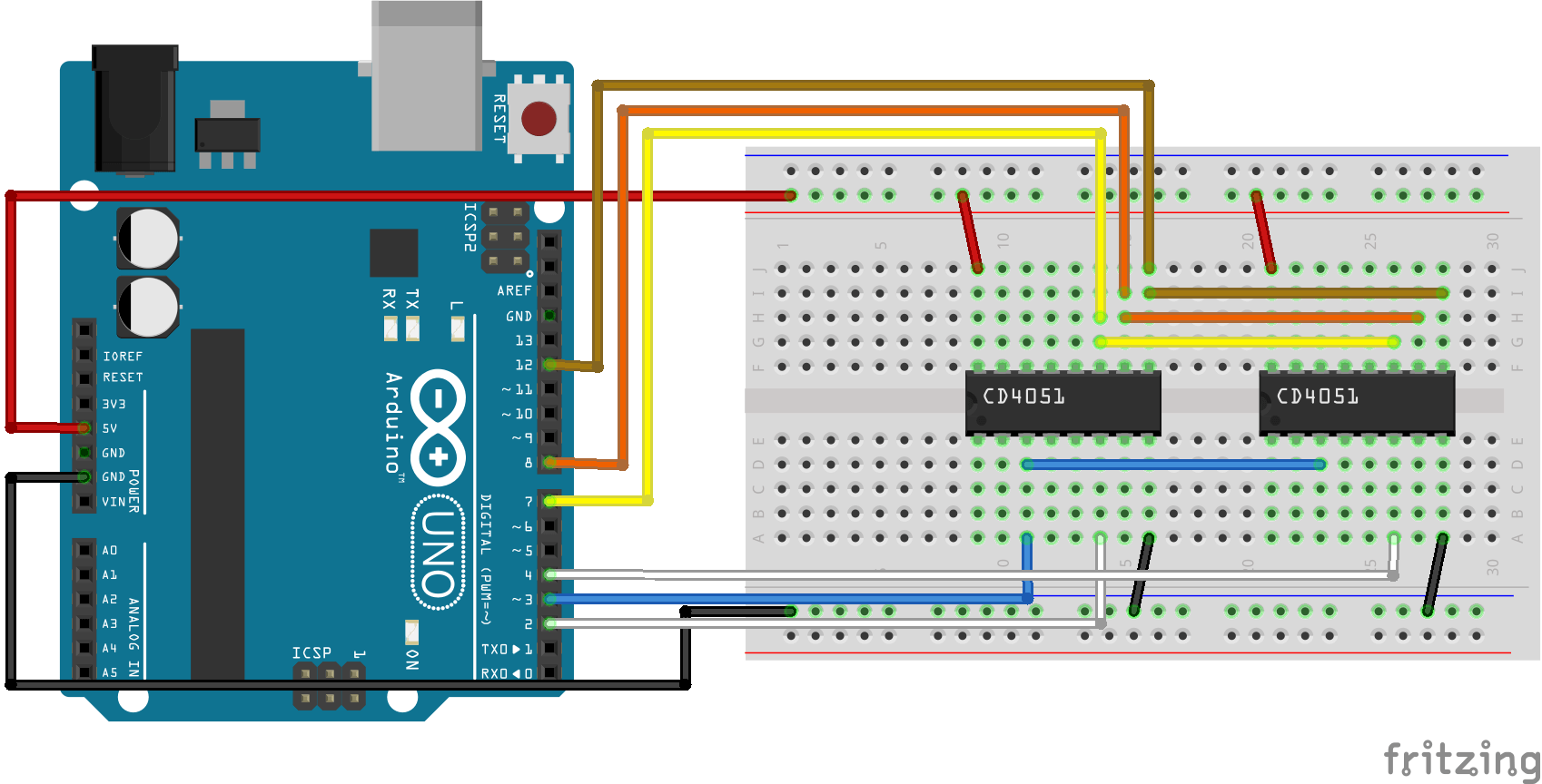
To further increase the number of inputs/outputs, it is possible to connect another multiplexer in parallel (several arrangements are possible).
Code
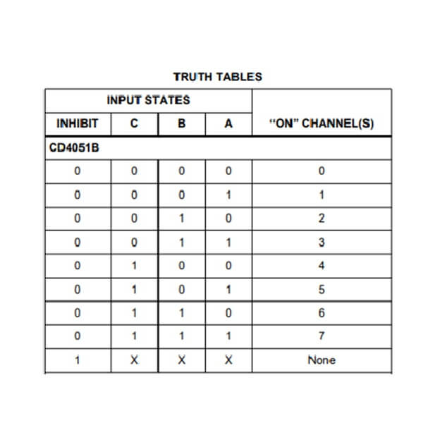
To select a channel on the multiplexer, we need to activate the integrated circuit by setting the INH pin to LOW, and setting the channels A,B and C to the values descripbed in the logic table.
//Constants
#define number_of_mux 1
#define numOfMuxPins number_of_mux * 8
#define enPin 2
#define channelA 4
#define channelB 7
#define channelC 8

//Parameters
const int comPin  = 3;

void setup(){
//Init Serial USB
Serial.begin(9600);
Serial.println(F("Initialize System"));
//Init CD4051B
  pinMode(channelA, OUTPUT);
  pinMode(channelB, OUTPUT);
  pinMode(channelC, OUTPUT);
  pinMode(enPin, OUTPUT);
  digitalWrite(channelA, LOW);
  digitalWrite(channelB, LOW);
  digitalWrite(channelC, LOW);
  digitalWrite(enPin, LOW);
}

void loop(){
MuxLED();
}

void selectChannel(int chnl){/* function selectChannel */
//// Select channel of the multiplexer
  int A = bitRead(chnl,0); //Take first bit from binary value of i channel.
  int B = bitRead(chnl,1); //Take second bit from binary value of i channel.
  int C = bitRead(chnl,2); //Take third bit from value of i channel.
  digitalWrite(channelA, A);
  digitalWrite(channelB, B);
  digitalWrite(channelC, C);

  Serial.print(F("channel "));Serial.print(chnl);Serial.print(F(" : "));
  Serial.print(C);
  Serial.print(F(","));
  Serial.print(B);
  Serial.print(F(","));
  Serial.print(A);
  Serial.println();
}

void MuxLED(){/* function MuxLED */
//// blink leds
for(int i = 0; i <  numOfMuxPins; i++){
    selectChannel(i);
    Serial.print(F("LED "));Serial.print(i);Serial.println(F(" HIGH"));
    analogWrite(comPin,200);
    delay(200);
    Serial.print(F("LED "));Serial.print(i);Serial.println(F(" LOW"));
    analogWrite(comPin,0);
      }
}
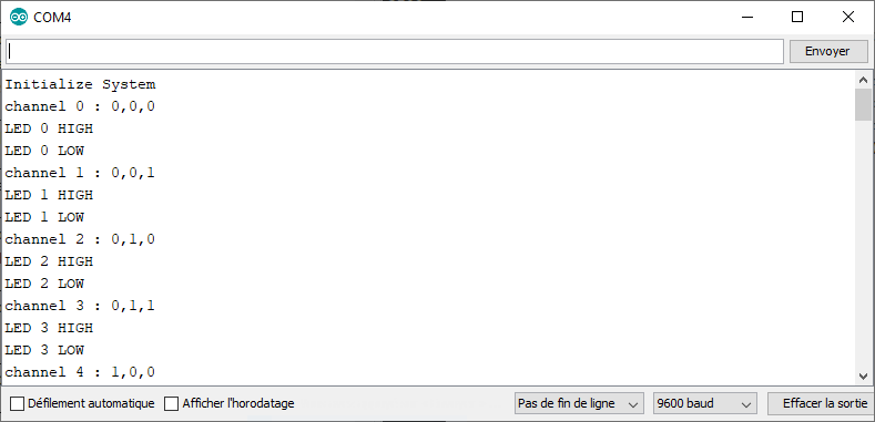
Results
It is possible with this simple component to increase the number of I/O of a microcontroller. Other circuit and code can be imagined to develop your own functionalities. Keep in mind that you can only select one channel at a time. This being said, make sure that this component correspond to your need
Applications
- Manage 8 LEDS using only 3 pins from the microcontroller
Sources
- https://fr.wikipedia.org/wiki/Multiplexeur
- http://www.ti.com/lit/ds/symlink/cd4051b.pdf
- https://www.aranacorp.com/en/programming-with-arduino/
Find other examples and tutorials in our Automatic code generator
Code Architect


Very usefull to undersatnd the CD 4051B. My digital knowledge is very basic.
Great post! I appreciate how you broke down the setup process for using a multiplexer with Arduino. The diagrams were really helpful, and I can’t wait to try this out in my next project!