In this tutorial, we will see how to manage several sensors with a shift register. We saw in the last tutorial on the subject, that the register could be used to drive LEDs. We will see here, how to read the value of 8 sensors on a single analog input. In electronics, the number of inputs and outputs becomes critical when using several sensors. The use of a shift register is a good solution to reduce the number of pins used.
In this article, we use the 74HC595 shift register but it is possible to use a multiplexer or a 74HC165 (Parallel to serial, more suitable for sensor reading)
Material
- Computer
- Arduino UNO
- USB cable A Male/B Male
- Shift Register 74HC595
Principle of operation
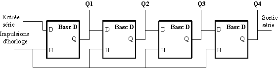
The shift register is an electronic component containing synchronous flip-flops. These are logic circuits which keep in memory a high or low state (like a bit) linked by the same clock. The principle of shift comes from the fact that we write or read in each memory bit by bit.
To manage sensors, we will use the output of the shift register as a voltage source and all sensor outputs will be connected to an analog input of the Arduino. The sensors will be powered one after the other which will allow us to retrieve, on the analog pin, the value of the powered sensor.
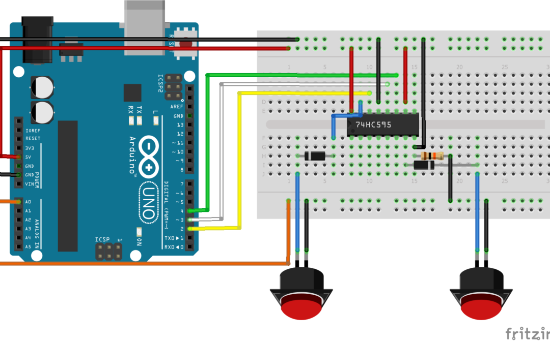
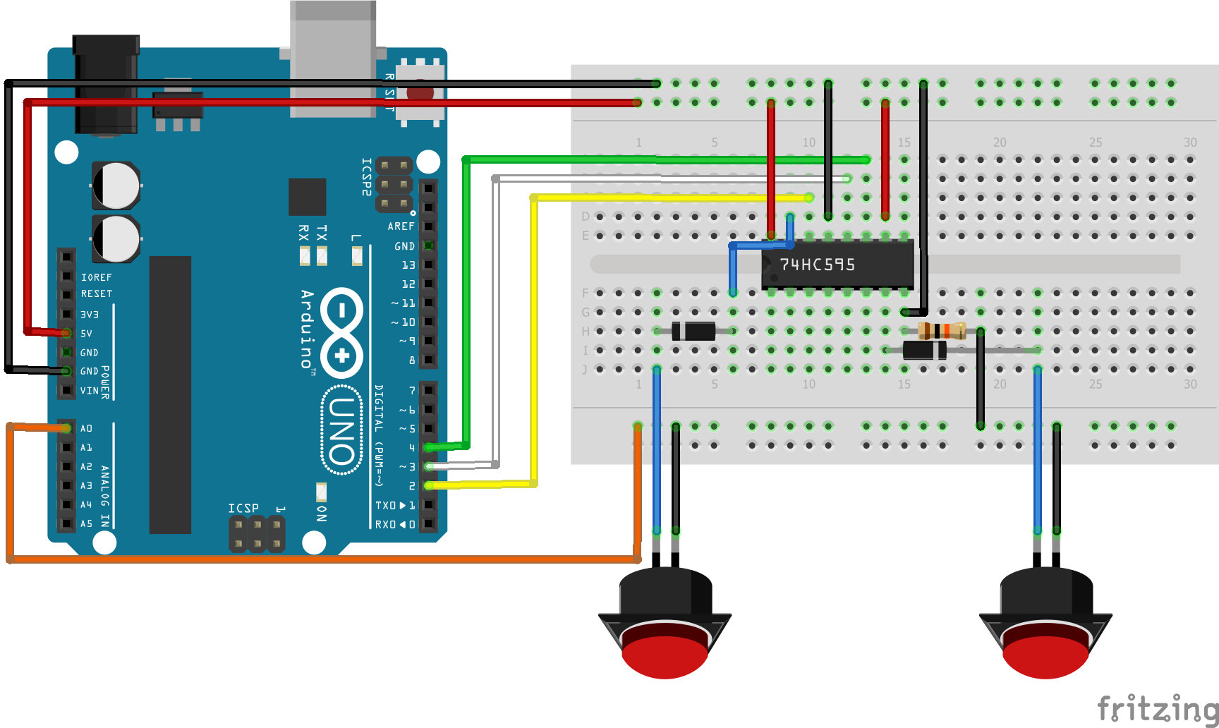
Scheme
The shift register requires 3 output pins of a microcontroller. It is possible to manage several registers connected in series.
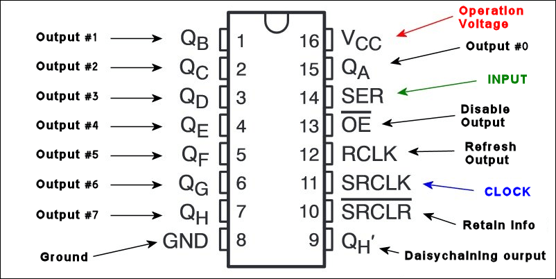
- GND Integrated circuit ground
- Vcc power supply pin. Usually connected to 5V
- SH_CP or RCLK shift register clock input. The register clock signal that determines whether the memory is written to
- ST_CP or SRCLK storage register clock input. The storage clock signal that defines in which memory we come to read or write.
- DS or SER serial data input. Signal containing the data to be recorded (UP or DOWN)
- Q0-Q7 parallel data output. Shift register output pins
- OE Output enable, active LOW. Pin connected to GND to activate the outputs
- MR Master reset, active LOW. Reset pin. Connected to 5V
- Q7′ serial data output (pin used only if multiple registers are connected in series)
Once the shift register is properly connected, we will connect each of the buttons. In order to be able to detect the state of several buttons, we need to add a diode to each output so that the current does not flow from one output to another of the shift register.
Code
To communicate with the shift register, we will juggle its input pins. We must set the RCLK pin low to write to a register. To write to the flip-flops, we must set the storage clock low. At each clock pulse, we go to the next flip-flop. To simplify our code, we will define this procedure in the writeRegister() function.
To manage the sensor group through the register, we will send pulses to each flip-flop and read the value of the button when the flip-flop is in the high state, that is, a current flows through the button.
//Constants
#define number_of_74hc595s 1
#define numOfRegisterPins number_of_74hc595s * 8
#define SER_Pin 2
#define RCLK_Pin 3
#define SRCLK_Pin 4

//Parameters
const int grpBtnPin = A0;

//Variables
boolean registers[numOfRegisterPins] = {0, 0, 0, 0, 0, 0, 0, 0};
boolean grpBtnState[numOfRegisterPins] = {0, 0, 0, 0, 0, 0, 0, 0};
boolean oldGrpBtnState[numOfRegisterPins] = {0, 0, 0, 0, 0, 0, 0, 0};
int grpBtnVal[numOfRegisterPins] = {0, 0, 0, 0, 0, 0, 0, 0};

void setup() {
  //Init Serial USB
  Serial.begin(9600);
  Serial.println(F("Initialize System"));
  //Init register
  pinMode(SER_Pin, OUTPUT);
  pinMode(RCLK_Pin, OUTPUT);
  pinMode(SRCLK_Pin, OUTPUT);
  pinMode(grpBtnPin, INPUT);
}

void loop() {
  readGrpBtn();
}

void clearRegisters() { /* function clearRegisters */
  //// Clear registers variables
  for (int i = numOfRegisterPins - 1; i >=  0; i--) {
    registers[i] = LOW;
  }
}

void writeRegisters() { /* function writeRegisters */
  //// Write register after being set
  digitalWrite(RCLK_Pin, LOW);
  for (int i = numOfRegisterPins - 1; i >=  0; i--) {
    digitalWrite(SRCLK_Pin, LOW); int val = registers[i];
    digitalWrite(SER_Pin, val);
    digitalWrite(SRCLK_Pin, HIGH);
  }
  digitalWrite(RCLK_Pin, HIGH);
}

void setRegisterPin(int index, int value) { /* function setRegisterPin */
  ////Set register variable to HIGH or LOW
  registers[index] = value;
}

void readGrpBtn() { /* function readGrpBtn */
  //// Read each btn
  for (int i = numOfRegisterPins - 1; i >=  0; i--) {
    grpBtnState[i] = false;
    setRegisterPin(i, HIGH);
    writeRegisters();
    delay(20);
    grpBtnVal[i] = analogRead(grpBtnPin);
    setRegisterPin(i, LOW);
    writeRegisters();

    if (grpBtnVal[i] > 500) {
      grpBtnState[i] = true;
      if (oldGrpBtnState[i] != grpBtnState[i]) {
        Serial.print(F("Btn "));
        Serial.print(i);
        Serial.print(F(" detected -> State =  "));
        Serial.println(grpBtnVal[i]);
      }
    }
  }
}
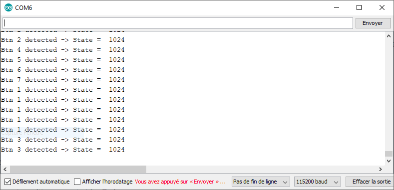
Results
The status of the button is updated each time it passes through the corresponding register memory and it is possible to read 8 buttons with a single analog input.
Applications
- Manage up to 8 sensors with three digital pins and one analog pin of a microcontroller
- Create an HID device with multiple keys
Find our shift register expansion module with simplified connectivity, compatible with all types of microcontrollers (Arduino, ESP8266, ESP32, Raspberry Pi etc.)
Sources
- https://fr.wikipedia.org/wiki/Registre_%C3%A0_d%C3%A9calage
- https://fr.wikipedia.org/wiki/Bascule_(circuit_logique)
- Use of a shift register
- Use of a Multiplexeur
Retrouvez nos tutoriels et d’autres exemples dans notre générateur automatique de code
La Programmerie


