Arduino can communicate with other devices via Bluetooth using the module HC-05 (master/slave). It enables the Arduino to connect and exchange data with other devices such as Smartphone, computer or other microcontrollers.Bluetooth communication can be used to control a robot remotely, Display and store data on your computer or on your smartphone, for instance.
Prerequisite: Arduino Serial communication
Material
- Computer
- Arduino UNO x2
- USB cable
- Bluetooth module HC-05 ZS-040 x2 (or 1x HC-05 and 1x HC-06)
- Dupont cables M/F
Module HC-05 overview
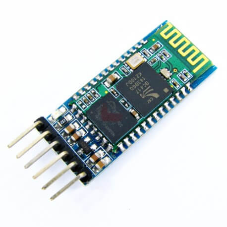
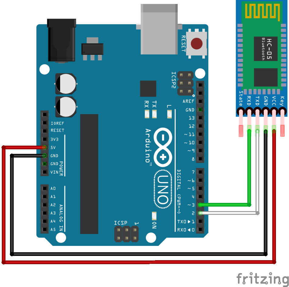
The Bluetooth module HC-05 has 6 pins, 2 for power, 2 to establish connection, 1 to enter configuration mode and the other to know the connection state.
- VCC power supply. Typically hooked up to 5V pin of the Arduino.
- GND ground. Typically hooked up to GND pin of the Arduino
- RX reception pin. Typically hooked up to transmission pin (TX) of the Arduino
- TX transmission pin. Typically hooked up to reception pin (RX) of the Arduino
- State is HIGH when the module is connected
- Key ou EN must be set to HIGH (3.3V) to enter configuration mode and must be disconnected to enter communication mode.
The particularity of the HC-05 is that it can be used as a slave module (equivalent to HC-06) and as a master module which means that it can pair itself to another device on its own.
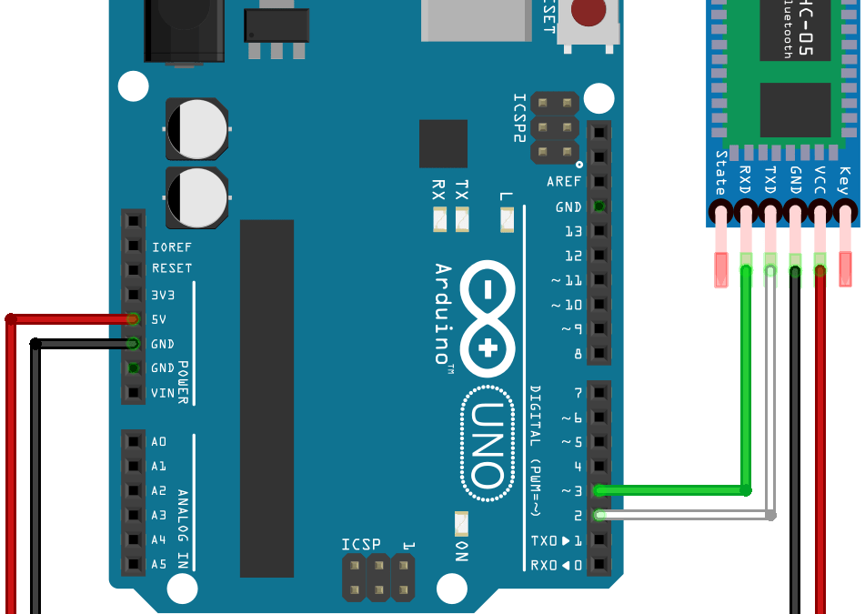
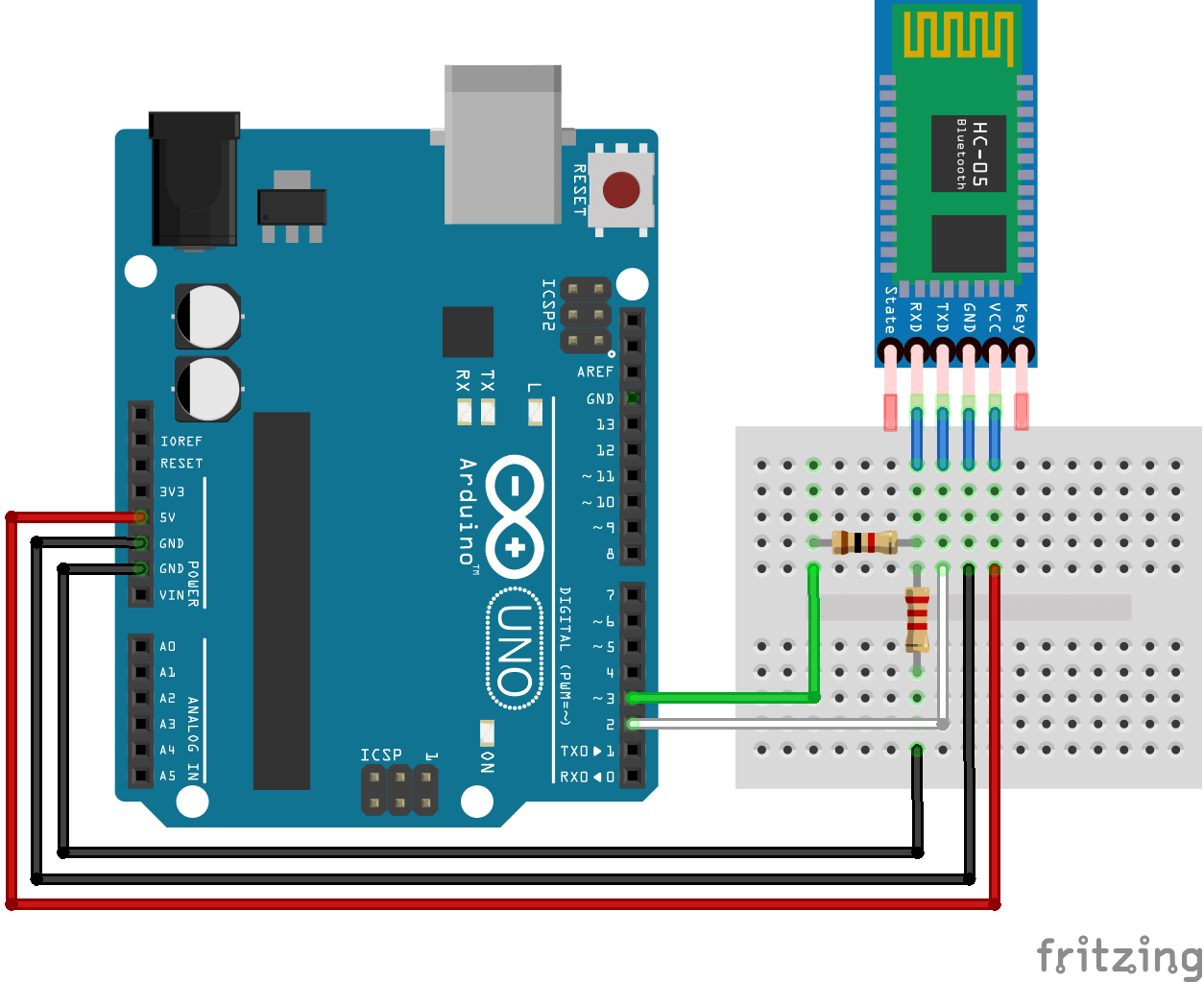
Schematics for configuration
WARNING :
- We use pin 2 and 3 of Arduino Uno. Depending on the microcontroller, some pins may not support SoftwareSerial communication. Especially, Arduino Mega, Micro and Leonardo. Check the documentation.
- Since the Bluetooth module is using 3.3V logic, it is advised to add a voltage divider to reduce the 5V voltage from Arduino. (resistor 1k between pin3 and Rx; 2k Ohm between Rx and GND).
Configuration of the module HC-05
Configuring the module HC-05 can be interesting to verify that it is working, hooked up correctly and to modify its parameters such as its name (useful when your are using several modules), PIN code and communication speed (baudrate). Especially if you want to use it as a master module. To allow configuration, the module HC-05 should be powered but not paired and the KEY/EN pin should be set to HIGH before module is switched on. When in configuration mode the LED will blink two seconds every two seconds.
Open the Serial monitor and select the end line option “New line” and a baudrate of 9600.
Note that HC-05 enter configuration mode with a baudrate of 38400bps.
Configuration code
The following code allows you to modify and check the parameters using the serial monitor and AT commands.
#include <SoftwareSerial.h>
#define rxPin 2
#define txPin 3
#define baudrate 38400

String msg;

SoftwareSerial hc05(rxPin ,txPin);

void setup(){
  pinMode(rxPin,INPUT);
  pinMode(txPin,OUTPUT);

  Serial.begin(9600);
  Serial.println("ENTER AT Commands:");
  hc05.begin(baudrate);
}

void loop(){
    readSerialPort();
    if(msg!="") hc05.println(msg);

    if (hc05.available()>0){
      Serial.write(hc05.read());
    }
}

void readSerialPort(){
  msg="";
 while (Serial.available()) {
   delay(10);
   if (Serial.available() >0) {
     char c = Serial.read();  //gets one byte from serial buffer
     msg += c; //makes the string readString
   }
 }
}
AT Commands
Compared to the module HC-06, the HC-05 can be used as a master module and you can also check the saved parameters using the AT commands.
In general, typing the command AT+<command>? will prompt the saved parameter (ex: AT+PSWD? will display the module PIN code). If you enter AT+<command>=<Param>, you can set the parameter value(ex: AT+PWSD=0000 to modify the PIN code to 0000).
Here are some of the AT commands:
- To test communication,enter AT in the serial monitor of the Arduino IDE. If everything is setup correctly it should display OK.
- To modify the module name, enter AT+NAME=<Param>. The module should answer OK (Defaut HC-05, Ex: To change the name to BTM1 enter AT+NAME=BTM1).
- To modify the PIN code, enter AT+PSWD=<Param> . The module should answer OK(Default 1234 Ex: To change the PIN to 0000 enter AT+PSWD=0000).
- AT+ROLE=<Param> to midy the role of the module as slave or master (Default 0, Ex: to change the role as master enter AT+ROLE=1, as slave enter AT+ROLE=0).
- To modify the baudrate, enter AT+UART=<Param1>,<Param2>,<Param3> with Param1, 2 and 3 serial communication parameters: baudrate, stop bit and parity bit respectively (By default,set to 9600,0,0. Ex: to modify the baudrate to 115200 enter AT+UART=115200,0,0).
Other AT commands exist for the Bluetooth module HC-05 that you can find following the link.
CAUTION: Different versions of the module HC-05 exist and the configuration procedure may vary. Be sure to check the module label and firmware version before use. For this tutorial, we used a module HC-05 labelled ZS-040 and firmware version 2.0-20100601.
N.B.: If module is not responding check wiring, cables conductivity and baudrate.
Do not hesitate to leave a comment or to contact us if you have issues configuring your HC-05 module.
Slave Configuration
To set the module as a slave, you can change the name as AT+NAME=HC05-Slave and choose the communication parameters and the PIN code that you want. You’ll need to make sure that master and slave as the same communication parameters.
- AT returns OK
- AT+NAME=HC05-Slave
- AT+UART=9600,0,0
- AT+ROLE=0
- Enter AT+ADDR to obtain the module address (ex: +ADDR:98d3:32:21450e)
For the slave module, you can also use a HC-06 module
Master Configuration
To set the module as master, you need to change the role and set the same communication parameter as the slave module.
- AT returns OK
- AT+NAME=HC05-Master
- AT+UART=9600,0,0
- AT+ROLE=1
- The slave module address must be enter in the master module to allows it to appair: AT+BIND=98d3,32,21450e (replace dots “:” by coma “,”)
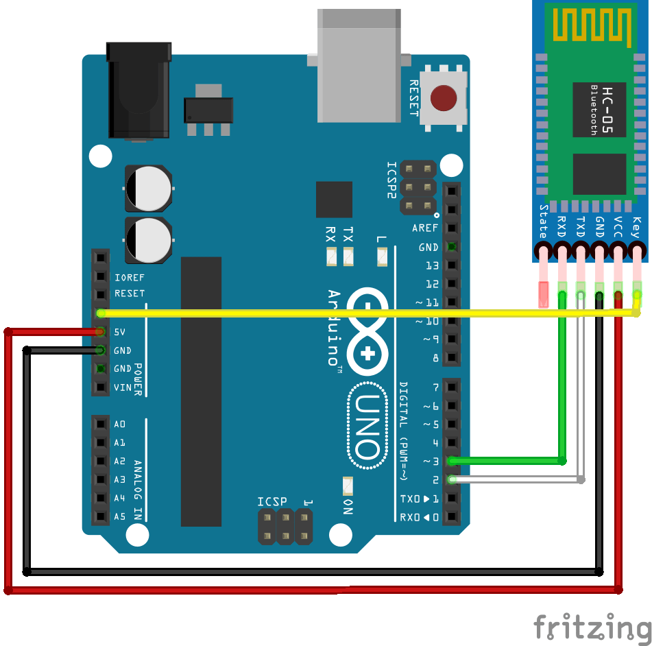
Schematics for communication
In communication mode, the Key/EN pin is not connected.
Communication Code
When both modules are configured, upload the following codes in to Arduino boards connected to your modules. Switch on the modules to enter communication mode. The master module should connect to the slave module and the LED should blink every second.
We use the same library SoftwareSerial.h as for the HC-06 module:
- SoftwareSerial hc05(Rx,Tx) to define the pins of the serial port
- hc05.begin() to define the baudrate (value should be the same as your module)
- hc05.available() to test if data are available in the buffer of the module
- hc05.read() to read data one byte at a time
- hc05.print() to send a string in ASCII form
- hc05.write() to send data one byte at a time
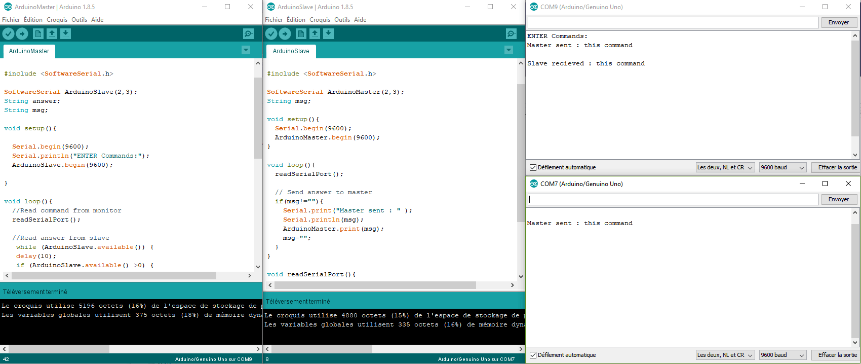
Master Code
#include <SoftwareSerial.h>

SoftwareSerial ArduinoSlave(2,3);
String answer;
String msg;

void setup(){

  Serial.begin(9600);
  Serial.println("ENTER Commands:");
  ArduinoSlave.begin(9600);

}

void loop(){
  //Read command from monitor
  readSerialPort();

  //Read answer from slave
   while (ArduinoSlave.available()) {
   delay(10);
   if (ArduinoSlave.available() >0) {
     char c = ArduinoSlave.read();  //gets one byte from serial buffer
     answer += c; //makes the string readString
   }
 }
  //Send data to slave
  if(msg!=""){
    Serial.print("Master sent : ");
    Serial.println(msg);
    ArduinoSlave.print(msg);
    msg="";
  }
  //Send answer to monitor
  if(answer!=""){
    Serial.print("Slave recieved : ");
    Serial.println(answer);
    answer="";
  }
}

void readSerialPort(){
 while (Serial.available()) {
   delay(10);
   if (Serial.available() >0) {
     char c = Serial.read();  //gets one byte from serial buffer
     msg += c; //makes the string readString
   }
 }
 Serial.flush();
}
Slave Code
#include <SoftwareSerial.h>

SoftwareSerial ArduinoMaster(2,3);
String msg;

void setup(){
  Serial.begin(9600);
  ArduinoMaster.begin(9600);
}

void loop(){
  readSerialPort();

  // Send answer to master
  if(msg!=""){
    Serial.print("Master sent : " );
    Serial.println(msg);
    ArduinoMaster.print(msg);
    msg="";
  }
}

void readSerialPort(){
 while (ArduinoMaster.available()) {
   delay(10);
   if (ArduinoMaster.available() >0) {
     char c = ArduinoMaster.read();  //gets one byte from serial buffer
     msg += c; //makes the string readString
   }
 }
 ArduinoMaster.flush();
}
If you open both serial monitors and if you enter a command in the master board monitor, you should see the following results. The master board send a command which is recieved and sent back by the slave board. The communications works correctluy in both directions.
If you have issues configuring or pairing your Bluetooth modules, do not hesitate to contact us or to leave a comment.
Application
Source
- Communicate with Arduino
- Software Serial Example
- Using a HC-06 module with Arduino
- Bluetooth Module HC-05
- AT Commands
- Create an application using App Inventor 2
Find other examples and tutorials in our Automatic code generator
Code Architect


i tried to type AT commands on arduino uno and lilypad (after uploading this code) and it worked but it has problem with arduino mega, “ENTER AT Commands:” is written on serial monitor but after i send AT its not outputing anything even errors.
Hi,
Try another set of pins. Arduino Mega has different SoftwareSerial pins compatility. In the documentation :
Not all pins on the Mega and Mega 2560 support change interrupts, so only the following can be used for RX: 10, 11, 12, 13, 14, 15, 50, 51, 52, 53, A8 (62), A9 (63), A10 (64), A11 (65), A12 (66), A13 (67), A14 (68), A15 (69).
Let me know if it works
sorry for late answer, it worked perfectly thank you very much and if you have time it will be very helpful to give give me code for my project so i have simple switch on/off button on master device and LED on slave and i want want to turn that LED on and off with that button, thank you again, I really appreciate this!
Nvm i did it thx you anyway
Hi i m arif actually on the shop itself i by mistake clicked the reset button and now it is not showing anything and i m not able to connect it with my mobile phone…….. plz do reply and suggest me the solution for it. I m waiting for your reply. Thnk you
Which reset button did you click? Arduino’s or the one on HC05 module? Can you power it down and back and see if something change?
Can both the pin no 2 & 3 be configured as Tx. As my motive is to connect my both Left & Right speakers to the module. Will it work ? or suggest the solution/code for the same.
Both can be configured as Tx but you still need to define Rx pins. I have never tried to connect two Bluetooth modules to an Arduino. Wouldn’t it be better to send both channels over one Bluetooth connexion?
i tried your configuration the master sent the message i type in the serial monitor but the slave cannot receive the message i sent.
Hello, are the modules connected? Does it receive something?
Would I need a voltage divider circuit if implementing with a Arduino Mega
The setup is the same on Arduino UNO and Arduino Mega. It is advised to use a voltage divider but you can try without.
I think there’s an error in the code. In the schematic, you connected pin 2 to TX and pin 3 to RX, but in the code you set them as
#define rxPin 2
#define txPin 3
Hi, thanks for your command. This is no error.
In Serial communication, microcontroller Rx (reception) is hooked to module Tx(transmission) and micro Tx hooked to module Rx.
I have set everything up as explained in the article and yet I cant get any connection between the modules. The lights are blinking together indicating they are paired, all baud rates (including for the hc-05’s) are set to 9600, the master will say it sent whatever I type into the serial monitor but nothing comes up from the slave and I never get a response. Any idea why this might happen? I’ve been trying different combinations of things for 2 days with this thing.
same here. I done everything the details but still cannot received to the slave message.
Me, too. I don’t if it has anything to do with the blinking. I saw that in another video, one module would blink after the other finished blinking. But in my case, both modules are pretty much blinking at the same time, with a very slight almost unnoticeable delay.
Thanks